|
|
|

|
|
| Search | Car Forums | Gallery | Articles | Helper | AF 350Z | IgorSushko.com | Corporate |
|
| Latest | 0 Rplys |
 07-13-2006, 10:27 PM
|
#16 | |
|
Resident Chemist
 
Join Date: Feb 2004
Location: Rockville, Maryland
Posts: 8,586
Thanks: 105
Thanked 157 Times in 157 Posts

|
Re: 4Runner FAQs
Tacoma/4Runner Differential References
Thanks to Flash75 for the following information: This links covers differential information for most Toyota truck applications. If covers ratios and how to determine your ratio, the various types of differentials and their applications. Also covered are axle widths and Toyota electric locking differentials. http://home.4x4wire.com/erik/diffs/ Here are instructions for changing and setting up Toyota gears. The information should apply to all Toyota trucks. Great information for those who wish to change their gears. http://www.4x4wire.com/toyota/tech/gear_setup/ Tire Size and Gear Ratio Chart It lists the best combination for near stock, fuel economy and performance. http://toyota.off-road.com/toyota/article/articleDetail.jsp?id=186404
__________________
Forum Guidelines:http://www.automotiveforums.com/vbulletin/guidelines.html "What we've got here is a failure to communicate" |
|

|
|
07-13-2006, 10:28 PM
|
#17 | |
|
Resident Chemist
Join Date: Feb 2004
Location: Rockville, Maryland
Posts: 8,586
Thanks: 105
Thanked 157 Times in 157 Posts
|
Re: 4Runner FAQs
Good Exhaust System Information
http://www.nsxprime.com/FAQ/Miscellaneous/exhausttheory.htm Thanks to Flash75
__________________
Forum Guidelines:http://www.automotiveforums.com/vbulletin/guidelines.html "What we've got here is a failure to communicate" |
|
|
|
|
07-13-2006, 10:28 PM
|
#18 | |
|
Resident Chemist
Join Date: Feb 2004
Location: Rockville, Maryland
Posts: 8,586
Thanks: 105
Thanked 157 Times in 157 Posts
|
Re: 4Runner FAQs
Bleeding Brakes
How to bleed brakes. Link covers Toyota pickups and 4Runners. http://www.4x4wire.com/toyota/maintenance/bleedingbrakes/ Thanks to Flash75
__________________
Forum Guidelines:http://www.automotiveforums.com/vbulletin/guidelines.html "What we've got here is a failure to communicate" |
|
|
|
|
07-14-2006, 11:09 PM
|
#19 | |
|
Resident Chemist
Join Date: Feb 2004
Location: Rockville, Maryland
Posts: 8,586
Thanks: 105
Thanked 157 Times in 157 Posts
|
Re: 4Runner FAQs
TECHNICAL ARTICLES ON TOYOTA ENGINE SYSTEMS
EXTENSIVE AUTOMOTIVE INFORMATION LINKS Q: Where can I find technical information on my EGR system? I want to modify it and I'd better understand what's going on there first.  A: A good source of technical articles and automotive information links is Kevin Sullivan's Autoshop 101 site: http://www.autoshop101.com/ Here are the titles of his technical articles followed by direct links to the articles: Technical Articles Toyota Series - Electrical Electrical Fundamentals with questions.pdf http://www.autoshop101.com/forms/h1.pdf Electrical Circuits with questions.pdf http://www.autoshop101.com/forms/h2.pdf Electrical Components with questions.pdf http://www.autoshop101.com/forms/h3.pdf Analog vs Digital Meters with questions.pdf http://www.autoshop101.com/forms/h4.pdf Wire, Terminal and Connector Repair w/qu.pdf http://www.autoshop101.com/forms/h5.pdf Automotive Batteries with questions.pdf http://www.autoshop101.com/forms/h6.pdf Toyota Starting Systems with questions.pdf http://www.autoshop101.com/forms/h7.pdf Toyota Charging Systems with questions.pdf http://www.autoshop101.com/forms/h8.pdf Understanding Toyota Wiring Diagram.pdf http://www.autoshop101.com/forms/h09e.pdf Electrical Diagnostic Tools.pdf http://www.autoshop101.com/forms/h10e.pdf Diagnosing Body Electrical Problems.pdf http://www.autoshop101.com/forms/h11e.pdf Semiconductors with questions.pdf http://www.autoshop101.com/forms/h12.pdf Transistors with questions.pdf http://www.autoshop101.com/forms/h13.pdf Computers / Logic Gates with questions.pdf http://www.autoshop101.com/forms/h14.pdf Overview of Sensors & Actuators w/quest.pdf http://www.autoshop101.com/forms/h15.pdf Electronic Transmission #1 - Operation.pdf http://www.autoshop101.com/forms/h16.pdf Electronic Transmission #2 - Diagnosis w/quest.pdf http://www.autoshop101.com/forms/h17.pdf Shift Interlock System.pdf http://www.autoshop101.com/forms/h18.pdf Technical Articles Toyota Series - Engine Performance OBDI (pre-1996 5S-FE and pre-1994 V6) EFI#1 EFI System Overview.pdf http://www.autoshop101.com/forms/h20.pdf EFI#2 Air Induction System.pdf http://www.autoshop101.com/forms/h21.pdf EFI#3 Fuel Delivery & Injection Controls.pdf http://www.autoshop101.com/forms/h22.pdf EFI#4 Ignition System.pdf http://www.autoshop101.com/forms/h23.pdf Engine Controls #1 - Input Sensors.pdf http://www.autoshop101.com/forms/h24.pdf Engine Controls #2 - ECU/Outputs.pdf http://www.autoshop101.com/forms/h25.pdf Engine Controls #3 - Idle Speed Control.pdf http://www.autoshop101.com/forms/h26.pdf Engine Controls #4 - Diagnosis.pdf http://www.autoshop101.com/forms/h27.pdf Technical Articles Toyota Series - Engine Performance OBD-II (1996 and newer 5S-FE, and '94 and newer 1MZ-FE) Sensors#1 - Mode Sensors and Switches.pdf http://www.autoshop101.com/forms/h31.pdf Sensors#2 - Thermistors with questions.pdf http://www.autoshop101.com/forms/h32.pdf Sensors#3 - Position Sensors with questions.pdf http://www.autoshop101.com/forms/h33.pdf Sensors#4 - Air Flow Sensors with questions.pdf http://www.autoshop101.com/forms/h34.pdf Sensors#5 - Pressure Sensors with questions.pdf http://www.autoshop101.com/forms/h35.pdf Sensors#6 - Speed Sensors with questions.pdf http://www.autoshop101.com/forms/h36.pdf Sensors#6 - Oxygen / Air Fuel Sensors w/ques.pdf http://www.autoshop101.com/forms/h37.pdf Sensors#8 - Knock Sensors with questions.pdf http://www.autoshop101.com/forms/h38.pdf Ignition#1 - Ignition Overview w/questions.pdf http://www.autoshop101.com/forms/h39.pdf Ignition#2 - Electronic Spark Advance w/quest.pdf http://www.autoshop101.com/forms/h40.pdf Ignition#3 - Distributor / Distributorless w/qu.pdf http://www.autoshop101.com/forms/h41.pdf Fuel System#1 - Overview with questions.pdf http://www.autoshop101.com/forms/h42.pdf Fuel System#2 - Injection Duration w/ques.pdf http://www.autoshop101.com/forms/h43.pdf Fuel System#3 - Closed Loop /Fuel Trim w/qu.pdf http://www.autoshop101.com/forms/h44.pdf OBDII#1 - Overview of On-Board Diagnostics.pdf http://www.autoshop101.com/forms/h46.pdf OBDII#2 - Serial Data.pdf http://www.autoshop101.com/forms/h47.pdf OBDII#3 - Data Interpretation.pdf http://www.autoshop101.com/forms/h48.pdf Emission#1 - Chemistry of Combustion.pdf http://www.autoshop101.com/forms/h55.pdf Emission#2 - Emission Analysis.pdf http://www.autoshop101.com/forms/h56.pdf Emission#3 - Engine Sub Systems.pdf http://www.autoshop101.com/forms/h57.pdf Emission#4 - Closed Loop Feedback Systems.pdf http://www.autoshop101.com/forms/h58.pdf Emission#5 - Electronic Spark Advance.pdf http://www.autoshop101.com/forms/h59.pdf Emission#6 - Idle Speed Control Systems.pdf http://www.autoshop101.com/forms/h60.pdf Emission#7 - Exhause Gas Recirculation.pdf http://www.autoshop101.com/forms/h61.pdf Emission#8 - Evaporative Emission Control.pdf http://www.autoshop101.com/forms/h62.pdf Emission#9 - Positive Crankcase Ventilation.pdf http://www.autoshop101.com/forms/h63.pdf Emission#10 - Catalytic Converter.pdf http://www.autoshop101.com/forms/h64.pdf Emission#11 - Secondary Air.pdf http://www.autoshop101.com/forms/h65.pdf Don't ignore the information and links in the "Automotive Links" section. Also, the "Online Bookstore" is useful if you want to get ASE certified.
__________________
Forum Guidelines:http://www.automotiveforums.com/vbulletin/guidelines.html "What we've got here is a failure to communicate" |
|
|
|
|
07-14-2006, 11:13 PM
|
#20 | |
|
Resident Chemist
Join Date: Feb 2004
Location: Rockville, Maryland
Posts: 8,586
Thanks: 105
Thanked 157 Times in 157 Posts
|
Re: 4Runner FAQs
STARTER CLICKS ONCE BUT DOES NOT TURN ENGINE
Q: Often my starter will just click and not turn over the engine. It will do this for a long time, but eventually it will act normally. Is this a common problem with Toyotas? How can I fix it? A: Yes, it is a common problem with Toyota starters. Many times, the problem is sticking starter solenoid contacts. See the following links for descriptions on how to replace them. This is a really cheap and easy fix on a Tacoma and should be the first thing you try after you check all the cable connections and the battery quality. http://www.automotiveforums.com/vbul...d.php?t=166530 15 Toyota (NipponDenso now called Denso) starter-repair reference sites: http://www.4crawler.com/4x4/CheapTricks/Starter.shtml http://char.tuiasi.ro/vw/reality/rog...s/Starter.html http://yotarepair.com/startercontacts.html http://www.toyotaoffroad.net/afertig...rterrepair.htm http://www.4x4wire.com/toyota/maintenance/starter/ http://www.yotatech.com/~corey/tech/...r/haveblue.htm http://www.sleeoffroad.com/technical...er_rebuild.htm http://www.startercontacts.com/install.htm http://www.startercontacts.com/image...ded%20view.jpg http://www.colorado4x4.net/tech/star..._contacts.html http://www.barneymc.com/toy_root/techneek/starter.htm http://perso.wanadoo.fr/adherence.4x4/start_bj.htm http://www.automotiveforums.com/vbul...d.php?t=166530 http://www.toyotanation.com/forum/sh...312&forumid=10 http://www.toyotanation.com/showthre...312&forumid=10 Starter contact kits (8mm ID hole): Ace Electric # S-5263 (only two contacts) Ace Electric # S-5264 (only two contacts) Metro # 66-82104 (only two contacts) (www.metroautoinc.com ,Pomona,California) Toyota # 28226-72010/80 (battery side)(also1KZTE-2LT-1KZT) Toyota # 28226-72080 (8808-9108) Toyota # 28226-16130 (9108-9308) Toyota # 28226-55050 (9308-9511) Toyota # 28226-70040 (9308-9511) Toyota # 28226-72040 (motor side if needed) Toyota # 28226-72010 (8808-9511) Toyota # 28226-74070 (9108-9511) For others besides 22R series: Toyota # 28226-54220 (motor side) (2LTE, 3L..LN13# IKZTE, 2L#, KZN130,LN108,112,85..4FC) Toyota # 28226-54250 (Diesel Surf 2.4TD, contains a new end cover and gasket) Toyota # 28226-54320 (battery side) (2LTE, 3L..LN13# IKZTE, 2L#, KZN130, LN108,112,85..4FC,3B-1HZ-BJ73-HZJ7#-1KZT-KZJ70) Toyota # 28226-17030 (battery side) (1H#-HDJ80-HZJ80) Toyota # 28226-56250 (battery side) (3B-1HZ-1PZ-PZJ7#) Starter contacts only (8mm ID hole): Ace Electric # S-5231 Ace Electric # S-5293 (crescent moon shape) Ace Electric # S-5295 (crescent moon shape) Metro # 66-82106 (www.metroautoinc.com ,Pomona,California) Tons more at: http://www.metroautoinc.com/PDF%20Fi...%20Contact.pdf Toyota # 28226-70040 Wilson’s Electric # 45-29-652 Starter brushes: AC Delco # D762 GP Sorensen # 255048 Standard # JX-117 Whether your starter uses two rectangular types or one rectangular and one crescent you can substitute with two squares or one square and one crescent so any of the above part #'s for those kits will be the right ones, or about half of the auto electric shops in your local yellow pages would sell aftermarket contacts for only $5 each or the pair. Thanks to SydneyCanada for the above information STARTER CLICKS CONTINUOUSLY BUT DOES NOT TURN ENGINE Q: What if the starter clicks not once, but very fast and does not turn the engine over? A:The problem you're having is not the solenoid contacts as described above. With bad solenoid contacts, there is only one click (the starter relay), not many. Your problem is insufficient current/voltage getting to the starter. Most likely cause is a bad battery. Before you buy one, check the battery terminals - make sure they are on tight and they are clean. Check the connections on the other end of the battery cables for tightness and cleanliness also. If all looks good, replace the battery. If the battery cable connections are bad, loosen them from the battery and clean them with baking soda/water slurry until they are bright metal, then reconnect them and tighten them snug. Coat them with petroleum jelly to prevent them from corrosion. It it's possible something has been left on, like your headlights or dome light etc. and the battery may be drained/discharged, try charging it first or bring it in to have it tested before you buy a new one. BLOWER MOTOR FOR HEATER OR A/C DOES NOT WORK ON ALL SPEEDS Q: My blower motor doesn't work for the bottom three speeds. What is the problem - is it the motor or what? A: It is most likely a bad connection or bad resistor on the resistor block that controls the current to the motor. See the discussion in the following links: http://www.automotiveforums.com/vbul...d.php?t=252829 http://www.4crawler.com/4x4/CheapTricks/Blower.shtml
__________________
Forum Guidelines:http://www.automotiveforums.com/vbulletin/guidelines.html "What we've got here is a failure to communicate" Last edited by Brian R.; 05-16-2010 at 02:51 PM. |
|
|
|
|
07-14-2006, 11:18 PM
|
#21 | |
|
Resident Chemist
Join Date: Feb 2004
Location: Rockville, Maryland
Posts: 8,586
Thanks: 105
Thanked 157 Times in 157 Posts
|
Re: 4Runner FAQs
Thanks to yotarepair.com for alternative instuctional drawings:
TIMING BELT REPLACEMENT INSTRUCTIONS Q: My engine stopper running suddenly on the highway and now it won't start. Any guesses as to what the problem is? How do I replace my timing belt? What should I replace while I'm in there to save time in the future? A: It sounds like you may have broken your timing belt. If you can see the cam shafts by looking through the oil filler hole in the head cover, then you can use these as an indicator. If the cams don't turn when the engine is cranked, your timing belt is broken. You may have to remove the valve cover. Here are links to instructions for replacing the timing belt in various Tacoma engines: 2RZ-FE Timing Chain 3RZ-FE Timing Chain 5VZ-FE http://yotarepair.com/PDF%20files/5V..._belt_remo.pdf http://yotarepair.com/PDF%20files/5V..._belt_inst.pdf Another procedure: http://www.4x4wire.com/toyota/maintenance/timing_belt/ Additional Comments on Replacing Timing Belts Other than the timing belt whether or not you need more parts depends on if there are any fluid leaks inside the timing cover, the water pump may need to be replaced and there may be oil seals such as the front crankshaft seal or the camshaft seals that may be leaking and need to be replaced. If you do it yourself, make sure you understand how to set #1 piston at TDC on compression stroke. Also, be prepared to stop and put everything back together if you find you cannot remove the crank pulley bolt. I think this is the hardest part from a strength point of view. Air gun is best way. Really long cheater bar with tool to hold the crank is also good. A method of last resort is to position the breaker bar handle on the driver's side frame rail and just tap the starter with the plugs out. If the breaker bar handle is secure, the bolt will loosen. Don't use this method to completely back out the bolt, just to break it loose. Also, be careful and gentle with the new timing belt. Handle it as if it were a piece of gold foil. Don't bend it sharply, contaminate it with anything, or turn it inside out. Don't scratch the sensor part of the crankshaft timing pulley. Don't use the timing belt tension to tighten the mounting bolt of the camshaft timing pulley. If there is noticeable wear or cracks on the belt face, check to see if there are nicks on the side of the idler pulley lock. If there is wear or damage on only one side of the belt, check the belt guide and alignment of each pulley. If there is noticable wear on the belt teeth, check the timing cover for damage, correct gasket installation, and for foreign material on the pulley teeth. Check to make sure the idler pulley turns smoothly. If not, replace. Clean all the pulleys and keep them clean. If you have to turn the crankshaft, always turn it clockwise. Make sure you have all the gaskets you need. Clean the gasket surfaces to shiny metal everywhere before you replace the gaskets. Replace the timing cover gaskets if they are at all questionable. Make note of all the electical connections you disconnect when you disconnect them. Make sure they are all connected when you are done (DOH!). Check the accessory drive belts and replace them if they are old. Torque everything. INTERFERENCE ENGINES Q: What is an interference engine and is my Toyota engine an interference engine? Why should I care? A: An interference engine is one in which the valves and pistons can touch if the cams and crank are not kept in correct timing by the timing belt or chain. Most (not all) Toyota passenger car engines are free-running (non-interference engines). This means that if your timing belt breaks, then all that will happen is your engine will not run anymore until the belt is replaced. In an interference engine, piston-to-valve contact will cause very serious damage to the engine if the timing belt breaks. To see if your engine is an interference engine or not, look it up in the following brochure: http://www.gates.com/downloads/downl...older=brochure An asterisk opposite your engine means it is an interference engine.
__________________
Forum Guidelines:http://www.automotiveforums.com/vbulletin/guidelines.html "What we've got here is a failure to communicate" |
|
|
|
|
07-14-2006, 11:18 PM
|
#22 | |
|
Resident Chemist
Join Date: Feb 2004
Location: Rockville, Maryland
Posts: 8,586
Thanks: 105
Thanked 157 Times in 157 Posts
|
Re: 4Runner FAQs
SERVICE PUBLICATIONS
Q: Where can I purchase Toyota Service and Repair Manuals for my Tacoma? A: Printed copies of all Toyota, Scion, and Lexus service support information can be purchased directly from the Toyota Materials Distribution Center or MDC. The MDC stocks printed versions of most Toyota service information products, including legacy model information that is not available on this site. Note: Certain inventory items are produced in limited quantities and may not be reprinted or reissued once initial inventory is depleted. MDC telephone operators accept Visa and MasterCard credit card orders, Monday through Friday, 8 AM to 5 PM Pacific Time. To place orders call 1-800-622-2033 VARIOUS USED MANUALS - mostly older http://www.autobooksonline.com/ TRANSMISSION REPAIR MANUALS Q: Where can I purchase transmission repair manuals? A: http://www.autorepairmanuals.biz/sit...83/page/267592 RENT ONLINE ACCESS TO MANUALS HERE: http://www.eautorepair.net/ http://www.alldata.com/products/diy/index.html
__________________
Forum Guidelines:http://www.automotiveforums.com/vbulletin/guidelines.html "What we've got here is a failure to communicate" |
|
|
|
|
08-09-2006, 09:14 AM
|
#23 | |
|
Resident Chemist
Join Date: Feb 2004
Location: Rockville, Maryland
Posts: 8,586
Thanks: 105
Thanked 157 Times in 157 Posts
|
Re: 4Runner FAQs
HOW TO ADMINISTER SEAFOAM TO CLEAN YOUR ENGINE
(Thanks to Toysrme for the following discussion) Seafoam makes the world go round! Not really, but at $5 a can it's a steal. A can is 1 pint.  You need 2 cans. Pour 1/2 a can in the gas tank when you stop to fill up. (This ensures it mixes well) Pour the other 1/2 in with fresh engine oil. At the least you will notice that the engine will idle noticeably smoother. Here's where most people get confused. Using it down the intake to clean the combustion chamber & parts of the head. 1) Drive the car around the block until it comes up to temp 2) Pour 1/3 of a can into a separate container (1/4 of a can for 4 cylinders) 3) Crank the engine 4) Pull the brake booster hose off & put your finger over the end so the car doesn't lean out & stall.  5) Drop the hose in the bottom of the container & let your finger off the end. If the engine doesn't stall out completely SHUT IT OFF ASAP. The fluid will near instantly disappear & the engine should stall from being too rich to run, or being too lean from the hose letting air in afterwards. This will not break your engine. You're not using enough fluid to hydrolock it. 6) The engine should sit for 5 min. 7) Crank the engine & let it run until the smoke dies down Normally you will get an ungodly amount of smoke. 8) As the smoke dies down, drive the car around. Be sure to make liberal use of 1st & 2nd gear to get to the higher portions of the RPM range a few times. That would be 5000-6850rpm.. You are not breaking your engine by running it at those rpm... All of the computers on all of the engines will cut the fuel to slow the RPM down before the engine is damaged. Yes, they are built for it... Why someone would want to do this? To clean gunk, sludge, & misc. heavy buildup out of the oil system. Pump, passages, bearings, walls. To clean the fuel system. To clean carbon out of the combustion chamber. Now some people ask why you want to go to the trouble of cleaning carbon out of the engine. Because as it builds up on the valves, they don't seal as well - causing poor compression while the leaking gas superheats parts of the engine that are not designed for it. Because carbon in the combustion chamber is bad. mmmm kay? Any carbon becomes superheated. Superheated carbon / metal will cause the incoming fuel & air to ignite earlier than it should be. This (Detonation, pinging, kocking - all just names for pre-ignition) is very derailment to many aspects of engine life. This is what a 3vz-fe looks like @ 95,000 miles. (Forget the fluids, fluids spill look at the black carbon build-up) 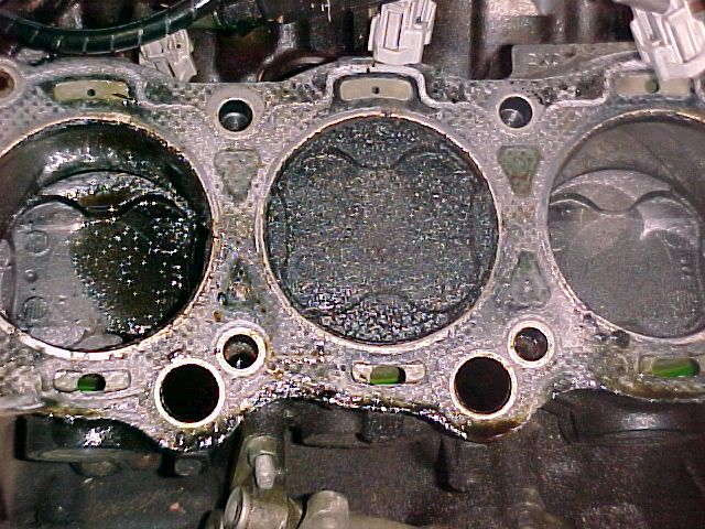 Here's what it looks like 6 months after the last 3 Seafoam treatments. 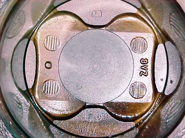 Seafoam = Good. It's cheap & versatile, while working at least as good as anything else; regardless of the cost. Brian R. note: GM Top Engine Cleaner is another useful additive for the above purpose.
__________________
Forum Guidelines:http://www.automotiveforums.com/vbulletin/guidelines.html "What we've got here is a failure to communicate" |
|
|
|
|
08-11-2006, 06:50 PM
|
#24 | |
|
Resident Chemist
Join Date: Feb 2004
Location: Rockville, Maryland
Posts: 8,586
Thanks: 105
Thanked 157 Times in 157 Posts
|
Toyota Approves Use of 0W-20 and 5W-20 GF-4 Oils
Toyota has approved the use of 5W20 GF-4 oils (e.g., Mobil1) in most modern engines, and 0W-20 in 2AZ-FE engines as shown in the folowing TSB.
I have been using the 5W-20 oil in my 5VZ-FE 4Runner engine for about 6 months now and can see the difference in mileage. It doesn't appear that either of these oils are approved for the 22R, 3S-FE or 5S-FE engine. I have been using a 50:50 mix of the 5W-20 and 5W-30 Mobil1 in my '96 5S-FE Camry for about 8k miles without any noticable problems. I have also notices a marked increase in mileage in this engine. I have been getting 410 miles/tank (about 27 mpg with 75:25 highway:city). I used to get around 360-375 miles per tank. 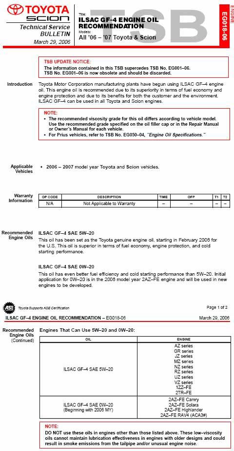
__________________
Forum Guidelines:http://www.automotiveforums.com/vbulletin/guidelines.html "What we've got here is a failure to communicate" Last edited by Brian R.; 08-18-2006 at 01:10 AM. |
|
|
|
|
08-12-2006, 04:59 PM
|
#25 | |
|
Resident Chemist
Join Date: Feb 2004
Location: Rockville, Maryland
Posts: 8,586
Thanks: 105
Thanked 157 Times in 157 Posts
|
Re: 4Runner FAQs
BUYING A CAR/TRUCK - WHAT TO LOOK FOR
Q: I'm about to purchase a mint vehicle, is there anything I should know about it before I purchase it. it only has 60k original miles. and great body. A: Timing belt may be due to be changed at 60K (or 90K), an added expense. Check the CV boots and see if they are torn - or grease has been thrown over the underbody in the area of the CV joints. Expensive repair. Check the color of the ATF. If it's really dirty, it may have never been changed and you may have a potential problem there. If it's mud, don't buy it. If it's just reddish brown, get it flushed as soon as you can. Make sure it shifts smoothly, quietly, and without a jerk. May indicate a problem. You should actually flush (not just drain & refill) all fluids ASAP after buying the car. Oil change, Transmission, Coolant, Brake lines, Powersteering fluid. Keep this expense in mind. Pull the oil filler cap and see if there is bright shiny metal visible or are there extensive black deposits, indicating a lack of maintenance. If there is alot of black crap visible, don't buy it. Check for oil leaks under the engine and transmission. Have the brakes checked and see if they need to be changed. That will be an added expense after you buy it. Tires are costlly also. Make sure there is no smoke or steam coming out of the exhaust, either when just starting it or after it is hot. May be a sign of having been overheated or other serious problem. Don't buy it. Check the coolant to make sure it is pretty red or green. No foam, bubbles in the overflow tank when the engine is running, or discoloration. If there are foam or bubbles - don't buy it. Engine should run smoothly and quietly, no jerking, hesitating, or "Check Engine" light showing. Check recent emissions results if available. Car should have no vibration at any speed. If there is any vibration, see if there is a bump in one of the tires. Anything else - don't buy it. If one of the tires has a bump, get it replaced as soon as possible. Take the cost of 4 tires into account if they are pretty used. You don't want one new tire on a set of badly used ones. On the test drive the vehicle should steer straight with no excessive side pull and the steering wheel should not be off center when driving on a straight road. Make allowances for an alignment and maybe front-end work if you find these indicators. Could be expensive. Bounce the car hard, front and back separately. If it doesn't stop bouncing immediately, you may need to buy a set of struts. This can be expensive. As a general rule, there should be nothing wrong with the struts at 60K. If the car is a relatively new model, it may indicate that the car has been abused (or the speedometer has been rolled back). If the car is really old, the struts may be shot due to age alone. Mileage is not the only indicator of the expected strut condition. An old car doesn't have to have been abused to have bad struts at low mileage. Along these lines: regardless of whether or not it has been driven hard, or sitting still, any car, regardless of make, can be expected to get around 10 years on the factory struts, springs, and rubber type mounts (i.e. strut mounts, bushings, engine mounts, etc.). And that it is fairly downhill quickly from there. Check under the car for shiny welds or a lot of new parts that may indicate the car has been extensively fixed because of a collision. Also check the dashboard and see if it has a VIN in front of the driver, no VIN number indicates it has been replaced - check the VIN against the title. Don't buy it if anything is wrong. Check the body panel fasteners. Example - Fender, Hood, Door, Trunk bolts, etc. Signs of chipped paint, disturbed mating surfaces, and tool usage may indicate that the vehicle has had body damage and been repaired. Run your fingers along the seams between the body panels. Wavyness or uneven spacing in the body panels indicates the presence of collision damage. Likewise, check the shock towers for welds, indicating repairs. Check all the lights, turn signals, cruise control (may be designed to work only above a certain speed), and other electrical components for proper operation. Also check that the air conditioning blows cold air and the heater works. If you don't know the car's history, check CARFAX.com for history. Only buy it if it has a squeeky clean history. There are other cars available that don't have potential serious problems. Don't take chances if there are unknown costs after the purchase. Don't buy it if there is any doubt about it's condition. Have a mechanic look at it - it is worth the money.
__________________
Forum Guidelines:http://www.automotiveforums.com/vbulletin/guidelines.html "What we've got here is a failure to communicate" Last edited by Brian R.; 08-13-2006 at 12:13 AM. |
|
|
|
|
08-24-2006, 02:05 AM
|
#26 | |
|
Resident Chemist
Join Date: Feb 2004
Location: Rockville, Maryland
Posts: 8,586
Thanks: 105
Thanked 157 Times in 157 Posts
|
Re: 4Runner FAQs
WHEEL BOLT PATTERN, LUG NUT THREAD SIZE, AND OFFSET
Q: I need some rims for the winter time and I came accross these. They came off a 06' Ford F150. They are 17's and the size he gave me was 6x135. Will they fit my '97 4Runner? A: No, the F-150 wheels won't fit. Not only do the bolt patterns have a different diameter, but the offset is wrong. F-150 6-135 and +44 offset 4Runner 6-139.7 and +08 offset Here is a link for any vehicle bolt pattern, thread size, and offset: http://www.racingdimension.com/RD_Wh...gnut_Chart.htm
__________________
Forum Guidelines:http://www.automotiveforums.com/vbulletin/guidelines.html "What we've got here is a failure to communicate" |
|
|
|
|
09-13-2006, 02:33 PM
|
#27 | |
|
Resident Chemist
Join Date: Feb 2004
Location: Rockville, Maryland
Posts: 8,586
Thanks: 105
Thanked 157 Times in 157 Posts
|
Re: 4Runner FAQs
TRANSMISSION FLUIDS
Q: My '94 4Runner is a little low in tranny fluid. I checked the book and it states using Dextron ll Automatic Tansmission Fluid. I have been to two different stores in the area and no one seems to have it. Is there another name that it goes by? What gives???? I even called the Toyota Dealer and he said that Dextron ll is the correct fluid for my '94 4Runner. What's going on? I feel as though I'm in a twilight zone!!!! I even checked Advance Auto online and there isn't a listing for it there either. Any help would be appreciated! A: You can use Dexron III anytime Dexron II was recommended. From Chevron.com: Maintaining Your Transmission These days there's no such thing as "normal" driving conditions. Heavy stop-and-go traffic, frequent short trips, trailer towing; they all put your engine to the supreme test and can take a toll on your transmission. Under these tough conditions, you can help your transmission run better and longer when you follow the vehicle manufacturer's severe service schedule and change the automatic transmission fluid at the recommended intervals (typically every 15,000 to 30,000 miles). Also, if you suspect that your ATF has oxidized or deteriorated between service intervals, you may want to consult with your local automotive service center. Selecting the proper quality of ATF is not as easy as it once was. In the past, ATF came in two types: DEXRON®, MERCON® or ATF Type F. However, as transmissions have become more advanced, automobile manufacturers have introduced fluids specifically designed for their transmissions. Always check your owner's manual for the required type of ATF. Here are the most commonly specified ATFs: DEXRON® -III This is a specification for General Motors vehicles, but many foreign manufactures specify a DEXRON approved ATF as well. DEXRON-III can be used in transmissions that call for DEXRON-IIE or DEXRON-II. MERCON® Most Ford vehicles manufactured between 1980 and 1999 specify a MERCON ATF. ATFs that meet DEXRON-III requirements usually meet the MERCON requirements as well. MERCON® V Beginning with the 1997 model year, Ford introduced a higher performance level ATF with the MERCON V specification. Many Ford automatic transmissions from 1999 on will require a MERCON V fluid. The most notable exceptions are the E40D, 4R100, and CD4E transmissions, which still specify regular MERCON ATF. Type F Type F is specifically designed for all pre-1977 Ford vehicles and some makes between 1977 and 1981. Effective March 1997, Ford discontinued administration of approvals for Type F fluids. However, there are still many vehicles on the road that use Type F. Type F and MERCON fluids are not interchangeable. ATF+3® /ATF+4® DaimlerChrysler has had their own ATF specifications for many years, but as of 1997, Chrysler owners' manuals no longer list DEXRON as an acceptable replacement. ATF+3 is a readily available mineral oil-based ATF that is suitable in any application calling for ATF PLUS® , ATF+2® , or a Type 7176® fluid. Vehicles manufactured after 1999 require ATF+4® , a synthetic-based ATF only available through DaimlerChrysler.
__________________
Forum Guidelines:http://www.automotiveforums.com/vbulletin/guidelines.html "What we've got here is a failure to communicate" |
|
|
|
|
09-17-2006, 04:00 AM
|
#28 | |
|
Resident Chemist
Join Date: Feb 2004
Location: Rockville, Maryland
Posts: 8,586
Thanks: 105
Thanked 157 Times in 157 Posts
|
Re: 4Runner FAQs
ALTERNATIVE REFRIGERANTS TO R12 AND R134A
Here is an interesting article on alternative refrigerants: A/C: New Alternative Refrigerants by Larry Carley If you have bought any R-12 refrigerant lately, you know it is pretty pricey stuff. Last year, the price peaked at about $20 a pound ($600 for a 30 lb. tank) in some areas of the country. This year some predict the price could shoot as high as $30 to $33 per lb. ($1000 per tank!) if we get a long hot summer. Consequently, people are searching for less expensive alternatives to recharge their A/C systems. NO DROP-INS Though some alternative refrigerants are being marketed as "drop-in" replacements for R-12, there is really no such thing. According to the EPA, the concept of a "drop-in" replacement for R-12 is a marketing myth. Such words imply a substitute refrigerant will perform the same as R-12 under all conditions, that it will require no modifications to the A/C system or changes in lubricant, and that it is compatible with R-12 and can be added to a system that still contains R-12. Federal law prohibits the topping off A/C systems with refrigerants that are different from what is in the systemunless all of the old refrigerant is first removed so the system can be converted to a new refrigerant. The truth is no substitute refrigerant meets all of these requirements. There are, however, a number of alternative refrigerants that have been reviewed by the EPA and have been found to meet the EPAs SNAP (Significant New Alternatives Policy) criteria for environmental acceptability and usage. The SNAP rules prohibit flammable refrigerants or ones that contain ozone-damaging CFCs. But just because a refrigerant meets the EPA's usage criteria does not mean it is endorsed or "approved" by the EPA, or that it will perform well as a refrigerant. THE ALTERNATIVES There are currently seven alternative refrigerants from which to choose. One is R-134a, which is the only alternative currently approved by all vehicle manufacturers worldwide for new vehicles as well as for converting older R-12 applications. The OEMS say R-134a can perform well in most R-12 systems provided the proper retrofit procedures are followed. The also recommend R-134a because it is a single component refrigerant, unlike most of the alternatives which are blends of two to four ingredients. The OEMS do not like blends because blends can undergo "fractionation." This is when the individual ingredients in a blend separate for various reasons. Fractionation can be caused by chemical differences between the refrigerants (lighter and heavier elements dont want to stay mixed), different rates of leakage through seals and hoses (smaller molecules leak at a higher rate than larger ones), and different rates of absorption by the compressor oil and desiccant. Fractionation is a concern because it can change the overall composition of the blend once it is in use, which can affect the performance characteristics of the refrigerant. Fractionation also makes it difficult to recycle a blended refrigerant because what comes out of the system may not be the same mix that went into the system. The OEMS also say limiting the alternatives to one (R-134a) simplifies things, reduces the risk of cross-contamination and eliminates the need for multiple recovery machines (EPA rules require a separate dedicated recovery only or recovery/recycling machine for each type of refrigerant serviced). BLENDS Alternative refrigerants that have been found acceptable for automotive applications or are currently being reviewed by the EPA include the following blends:
The suppliers of the alternative blends also insist the fractionation problem is exaggerated and do not foresee any major problems with recovering and recycling their products (recycling blends is currently illegal, but the EPA is reviewing its feasibility). Are blends establishing a niche in the marketplace? One supplier of these products said they sold over a million pounds of their alternative refrigerant last year alone! Most are predicting increased sales as the price of R-12 continues to rise and stockpiles dwindle. MACS FIELD STUDY A field study of various refrigerants conducted by the Mobile Air Conditioning Society (MACS) compared the cooling performance of R-12, R-134a and three blended refrigerants (Freeze 12, FRIGC and McCool Chill-It). The study found that all the alternative refrigerants (including R-134a) did not cool as well as R-12 in the vehicles tested (a 1990 Pontiac Grand Am and a 1987 Honda Accord). But the study did find that the blends outperformed R-134a in the Honda (but not the Pontiac). The increase in A/C outlet temperature with the different refrigerants ranged from less than a degree to almost 11 degrees. ILLEGAL REFRIGERANTS Another class of alternative refrigerants has also appeared on the scene: illegal refrigerants. Some products that have been introduced (OZ-12, HC-12a, R-176 and R-405a) do not meet the EPAs criteria for environmental acceptability or safety. Flammable refrigerants such as OZ-12 and HC-12a that contain large quantities of hydrocarbons (propane, butane, isobutane, etc.) have been declared illegal for use in mobile A/C applications, but are still turning up in vehicle systems anyway because of their cheap price. Flammable refrigerants pose a significant danger to a vehicles occupants should a leak occur. A spark from a cigarette or a switch can ignite the leaking refrigerant causing an explosion and turning the vehicles interior into an inferno. It only takes about four ounces of a flammable hydrocarbon refrigerant such as propane or butane to create an explosive mixture inside a typical automobile passenger compartment. Frontal collisions can also release the refrigerant if the condenser is damaged, which could result in a severe underhood fire causing extensive damage to the vehicle. Theres also a risk to service technicians who might encounter leaks while servicing a vehicle or operating recovery/recycling equipment. Merely topping off an A/C system with a flammable hydrocarbon can make the entire charge of refrigerant flammable if the amount added exceeds a certain percentage: 10% in the case of an R-12 system and only 5% with R-134a! Thats only three or four ounces of hydrocarbon depending on the overall capacity of the system. Flammable refrigerants are used in some stationary applications as well as truck trailer refrigeration units because theres less risk of leakage or fire. Also, the amount of refrigerant is typically much less, only five or six ounces total instead of several pounds. BOOTLEGGERS & COUNTERFEITERS Less dangerous but equally illegal is bootleg R-12 thats being smuggled into the U.S. from offshore. Though most of the industrialized nations have stopped manufacturing R-12 (production ended here December 31, 1995), R-12 is still being made in some Third World countries including Mexico. Some of this product is finding its way past customs in mislabeled containers or concealed in various ways. The EPA warns that much of the refrigerant it has confiscated thus far is of poor quality, contaminated by air, moisture, R-22 and other substances. The EPA has worked with customs authorities and the FBI to make a number of arrests. Fines for violating the clean air rules can run up to $25,000 per instance. Counterfeiting branded product is another scam thats being perpetrated to turn a fast buck in todays market. Cylinders of counterfeit Allied Signal Genetron R-12 have reportedly been turning up in various parts of the country. The cylinders do not contain R-12 but some "unknown" refrigerant. Allied Signal says the counterfeit boxes do not have cut-outs where lot numbers strapped on cylinders would appear and there are no bar codes or white painted stripes on the sides. The number "Q 1167" may also appear on the bottom of the packaging. The cylinders themselves may be marked with a pressure-sensitive decal whereas the genuine product has markings printed on the cylinder itself. CONTAMINATED REFRIGERANT The high price of R-12 has also lead to an increase in incidences of virgin R-12 being adulterated with other less expensive refrigerants. Most technicians assume a tank of virgin refrigerant is pure, but some are finding thats not the case. Some supplies say they now test every single tank of refrigerant to make sure it contains the proper refrigerant and that the quality of the refrigerant meets specifications. The primary threat of contamination, though, is that of accidentally cross-contaminating refrigerants when vehicles are professionally serviced. Because the law requires all refrigerants to be recovered, theres a potential risk of contaminating when recovery and recycling equipment is connected to a vehicle. The problem is compounded, many say, by the proliferation of alternative and illegal refrigerants. The dangers of cross-contamination are the effects it can have on cooling performance and component reliability. R-12 and R-134a are not compatible refrigerants because R-134a will not mix with and circulate mineral-based compressor oil (which may lead to compressor failure). Nor is R-134a compatible with the moisture-absorbing desiccant XH-5, which is used in many R-12 systems. Intermixing refrigerants can also raise compressor head pressures dangerously. Adding R-22 (which is used in many stationary A/C systems but is not designed for use in mobile A/C applications) to an R-12 or R-134a system may raise head pressures to the point where it causes the compressor to fail. Straight R-22 can cause extremely high discharge pressure readings (up to 400 or 500 psi!) when underhood temperatures are high. R-22 is also not compatible with XH-5 and XH-7 desiccants used in most mobile A/C systems. R-134a also requires its own special type of oil: either a polyakylene (PAG) oil or a polyol ester (POE) oil. The OEMS mostly specify a variety of different PAG oils because some compressors require a heavier or lighter viscosity oil for proper lubrication (though General Motors does specify only a single grade of PAG oil for most service applications). The aftermarket generally favors POE oil because POE is compatible with both R-12 and R-134a and unlike PAG oil it will mix with mineral oil. Mineral oil, as a rule, should still be used in older R-12 systems. DECISIONS, DECISIONS The use of alternative refrigerants such as blends will likely grow because theyre a cheap alternative to R-12. The OEMs dont like it, but the EPA has said it will let the market decide the fate of alternative blends. Consequently, you need to be aware of whats potentially out there and be prepared to handle (or not handle) blends. To minimize the risk of cross-contamination, the EPA requires that each type of refrigerant (including blends) have unique service fittings (permanently installed) and proper labeling. The EPA also requires shops to use a separate dedicated recovery/recycling machine for R-12 and R-134a, plus one or more additional recovery only machines for any other refrigerants that might be used. For this reason, many shops may choose to avoid blends. But fleets may find blends to be an acceptable alternative if they dont want to convert (or it would cost too much to convert) their vehicles over to R-134a. To protect recycling equipment and customers vehicles against cross-contamination or bad refrigerant, service facilities should use a refrigerant identifier to check every vehicle before it is serviced. An identifier can also help the shop monitor the quality of their recycled refrigerant as well as any virgin refrigerant that might be purchased. Most identifiers that are available today can only tell you if the system contains pure R-12, R-134a, hydrocarbons, or R-22 or an "unknown" refrigerant. Each blend has its own characteristic finger print, but because of the fractionation problem getting a precise fix on exactly whats in a vehicle isnt as easy as it sounds. The best advise is this: if you dont know what type of refrigerant is in your vehicle, take it to a shop that has a refrigerant identifier and have it checked. Intermixing different refrigerants can cause cooling problems as well as shorten the life of the compressor. CONTAMINATION ALERT! As the use of alternative refrigerants grows, so does the risk of cross-contamination. A recent survey by the Florida EPA revealed some startling results. When they tested the refrigerant recovery tanks in about 100 shops, heres what they found: Thirty-eight percent of the recovery tanks showed some type of contamination! Independent repair garages and service shops had the lowest rate of contamination, but it was still 32% (nearly one out of three). Used car dealers were the worst, with 71% of their recovery tanks (almost three out of four) showing signs of contamination. Air contamination was the worst problem, being present in 22% of the tanks tested overall. But cross-contamination between R-12 and R-134a was also found in 15% of the tanks. The most cross-contamination (29%) was discovered in used car dealers. RETROFIT OR NOT? The OEMS say R-12 should be used in all R-12 systems as long as it is available because R-12 provides the best cooling performance in these applications. They say theres no need to retrofit to R-134a or to use any other refrigerant as long as the system is cooling normally. But if the system requires major repairs such as a new compressor or condenser, the cost to retrofit may be justified. The OEMS say switching an older R-12 system to R-134a does not require a lot of modifications in many instances. Changing the accumulator or receiver-dryer, removing the old compressor oil and replacing the high pressure switch is generally all thats neededa job that can usually be done for less than $200. For more information, consider purchasing the R134A RETROFIT GUIDE on this website. OEM as well as aftermarket retrofit kits are now available for such conversions. But some vehicles (namely those with viton compressor seals, compressors that cant handle higher head pressures or have small condensers) arent so easy to convert. Changing some of these vehicles over to R-134a requires extensive and expensive modifications. So for these applications there are no kits or easy answersother than to switch to a blend refrigerant if R-12 becomes too expensive or is unavailable.
__________________
Forum Guidelines:http://www.automotiveforums.com/vbulletin/guidelines.html "What we've got here is a failure to communicate" |
|
|
|
|
09-17-2006, 08:03 PM
|
#29 | |
|
Resident Chemist
Join Date: Feb 2004
Location: Rockville, Maryland
Posts: 8,586
Thanks: 105
Thanked 157 Times in 157 Posts
|
Re: 4Runner FAQs
OBDII DTC CODES
A primer on OBDII DTC codes: http://www.overboost.com/story.asp?id=1286&r=1 See also: http://www.obd-codes.com/trouble_codes/index.php Here are a list of generic and Toyota-specific DTC codes from http://www.iequus.com/assets/manuals/3100E.pdf DTC Codes in BOLD have troubleshooting guide at the end of this post. The above document also provided Manufacturer-specific DTC codes for Honda, General Motors, Ford, and Chrysler. DIAGNOSTIC TROUBLE CODE DEFINITIONS The following Diagnostic Trouble Code Definitions lists represent the most complete information currently available. OBD II is an evolving system, and new codes and definitions will be added as the system matures. ALWAYS consult the vehicles service manual for code definitions not included in these lists. The following code definition lists provide both Generic Diagnostic Trouble Code Definitions and Manufacturer-Specific Diagnostic Trouble Code Definitions for the following vehicles: OBD II Powertrain GENERIC (P0XXX) Diagnostic Trouble Codes. OBD II Generic Diagnostic Trouble Codes and their definitions apply to all makes and models of import and domestic vehicles that are OBD II COMPLIANT. OBD II Powertrain MANUFACTURER SPECIFIC (P1XXX) Diagnostic Trouble Codes. OBD II Manufacturer-Specific Diagnostic Trouble Codes and their definitions apply only to vehicles produced by the specific manufacturer (Ford, GM, Toyota etc.). GENERIC OBD II CODE DEFINITIONS P0010 "A" Camshaft Position Actuator Circuit (Bank 1) P0011 "A" Camshaft Position - Timing Over-Advanced or System Performance (Bank 1) P0012 "A" Camshaft Position - Timing Over-Retarded (Bank 1) P0013 "B" Camshaft Position - Actuator Circuit (Bank 1) P0014 "B" Camshaft Position - Timing Over-Advanced or System Performance (Bank 1) P0015 "B" Camshaft Position - Timing Over-Retarded (Bank 1) P0020 "A" Camshaft Position Actuator Circuit (Bank 2) P0021 "A" Camshaft Position - Timing Over-Advanced or System Performance (Bank 2) P0022 "A" Camshaft Position - Timing Over-Retarded (Bank 2) P0023 "B" Camshaft Position - Actuator Circuit (Bank 2) P0024 "B" Camshaft Position - Timing Over-Advanced or System Performance (Bank 2) P0025 "B" Camshaft Position - Timing Over-Retarded (Bank 2) P0030 HO2S Heater Control Circuit (Bank 1 Sensor 1) P0031 HO2S Heater Control Circuit Low (Bank 1 Sensor 1) P0032 HO2S Heater Control Circuit High (Bank 1 Sensor 1) P0033 Turbo Charger Bypass Valve Control Circuit P0034 Turbo Charger Bypass Valve Control Circuit Low P0035 Turbo Charger Bypass Valve Control Circuit High P0036 HO2S Heater Control Circuit (Bank 1 Sensor 2) P0037 HO2S Heater Control Circuit Low (Bank 1 Sensor 2) P0038 HO2S Heater Control Circuit High (Bank 1 Sensor 2) P0042 HO2S Heater Control Circuit (Bank 1 Sensor 3) P0043 HO2S Heater Control Circuit Low (Bank 1 Sensor 3) P0044 HO2S Heater Control Circuit High (Bank 1 Sensor 3) P0050 HO2S Heater Control Circuit (Bank 2 Sensor 1) P0051 HO2S Heater Control Circuit Low (Bank 2 Sensor 1) P0052 HO2S Heater Control Circuit High (Bank 2 Sensor 1) P0056 HO2S Heater Control Circuit (Bank 2 Sensor 2) P0057 HO2S Heater Control Circuit Low (Bank 2 Sensor 2) P0058 HO2S Heater Control Circuit High (Bank 2 Sensor 2) P0062 HO2S Heater Control Circuit (Bank 2 Sensor 3) P0063 HO2S Heater Control Circuit Low (Bank 2 Sensor 3) P0064 HO2S Heater Control Circuit High (Bank 2 Sensor 3) P0065 Air Assisted Injector Control Range/Performance P0066 Air Assisted Injector Control Circuit or Circuit Low P0067 Air Assisted Injector Control Circuit High P0070 Ambient Air Temperature Sensor Circuit P0071 Ambient Air Temperature Sensor Range/Performance P0072 Ambient Air Temperature Sensor Circuit Low Input P0073 Ambient Air Temperature Sensor Circuit High Input P0074 Ambient Air Temperature Sensor Circuit Intermittent P0075 Intake Valve Control Solenoid Circuit (Bank 1) P0076 Intake Valve Control Solenoid Circuit Low (Bank 1) P0077 Intake Valve Control Solenoid Circuit High (Bank 1) P0078 Exhaust Valve Control Solenoid Circuit (Bank 1) P0079 Exhaust Valve Control Solenoid Circuit Low (Bank 1) P0080 Exhaust Valve Control Solenoid Circuit High (Bank 1) P0081 Intake Valve Control Solenoid Circuit (Bank 2) P0082 Intake Valve Control Solenoid Circuit Low (Bank 2) P0083 Intake Valve Control Solenoid Circuit High (Bank 2) P0084 Exhaust Valve Control Solenoid Circuit (Bank 2) P0085 Exhaust Valve Control Solenoid Circuit Low (Bank 2) P0086 Exhaust Valve Control Solenoid Circuit High (Bank 2) P0100 Mass or Volume Air Flow Circuit Malfunction P0101 Mass or Volume Circuit Range/Performance Problem P0102 Mass or Volume Circuit Low Input P0103 Mass or Volume Circuit High Input P0104 Mass or Volume Circuit Intermittent P0105 Manifold Absolute Pressure/Barometric Pressure Circuit Malfunction P0106 Manifold Absolute Pressure/Barometric Pressure Circuit Range/Performance Problem P0107 Manifold Absolute Pressure/Barometric Pressure Circuit Low Input P0108 Manifold Absolute Pressure/Barometric Pressure Circuit High Input P0109 Manifold Absolute Pressure/Barometric Pressure Circuit Intermittent P0110 Intake Air Temperature Circuit Malfunction P0111 Intake Air Temperature Circuit Range/Performance Problem P0112 Intake Air Temperature Circuit Low Input P0113 Intake Air Temperature Circuit High Input P0114 Intake Air Temperature Circuit Intermittent P0115 Engine Coolant Temperature Circuit Malfunction P0116 Engine Coolant Temperature Circuit Range/Performance Problem P0117 Engine Coolant Temperature Circuit Low Input P0118 Engine Coolant Temperature Circuit High Input P0119 Engine Coolant Temperature Circuit Intermittent P0120 Throttle/Pedal Position Sensor/Switch A Circuit Malfunction P0121 Throttle/Pedal Position Sensor/Switch A Circuit Range/Performance Problem P0122 Throttle/Pedal Position Sensor/Switch A Circuit Low Input P0123 Throttle/Pedal Position Sensor/Switch A Circuit High Input P0124 Throttle/Pedal Position Sensor/Switch A Circuit Intermittent P0125 Insufficient Coolant Temperature for Closed Loop Fuel Control P0126 Insufficient Coolant Temperature for Stable Operation P0127 Intake Air Temperature Too High P0128 Coolant Thermostat (Coolant Temperature Below Thermostat Regulating Temperature) P0130 O2 Sensor Circuit Malfunction (Bank 1 Sensor 1) P0131 O2 Sensor Circuit Low Voltage (Bank 1 Sensor 1) P0132 O2 Sensor Circuit High Voltage (Bank 1 Sensor 1) P0133 O2 Sensor Circuit Slow Response (Bank 1 Sensor 1) P0134 O2 Sensor Circuit No Activity Detected (Bank 1 Sensor 1) P0135 O2 Sensor Heater Circuit Malfunction (Bank 1 Sensor 1) P0136 O2 Sensor Circuit Malfunction (Bank 1 Sensor 2) P0137 O2 Sensor Circuit Low Voltage (Bank 1 Sensor 2) P0138 O2 Sensor Circuit High Voltage (Bank 1 Sensor 2) P0139 O2 Sensor Circuit Slow Response (Bank 1 Sensor 2) P0140 O2 Sensor Circuit No Activity Detected (Bank 1 Sensor 2) P0141 O2 Sensor Heater Circuit Malfunction (Bank 1 Sensor 2) P0142 O2 Sensor Circuit Malfunction (Bank 1 Sensor 3) P0143 O2 Sensor Circuit Low Voltage (Bank 1 Sensor 3) P0144 O2 Sensor Circuit High Voltage (Bank 1 Sensor 3) P0145 O2 Sensor Circuit Slow Response (Bank 1 Sensor 3) P0146 O2 Sensor Circuit No Activity Detected (Bank 1 Sensor 3) P0147 O2 Sensor Heater Circuit Malfunction (Bank 1 Sensor 3) P0148 Fuel Delivery Error P0149 Fuel Timing Error P0150 O2 Sensor Circuit Malfunction (Bank 2 Sensor 1) P0151 O2 Sensor Circuit Low Voltage (Bank 2 Sensor 1) P0152 O2 Sensor Circuit High Voltage (Bank 2 Sensor 1) P0153 O2 Sensor Circuit Slow Response (Bank 2 Sensor 1) P0154 O2 Sensor Circuit No Activity Detected (Bank 2 Sensor 1) P0155 O2 Sensor Heater Circuit Malfunction (Bank 2 Sensor 1) P0156 O2 Sensor Circuit Malfunction (Bank 2 Sensor 2) P0157 O2 Sensor Circuit Low Voltage (Bank 2 Sensor 2) P0158 O2 Sensor Circuit High Voltage (Bank 2 Sensor 2) P0159 O2 Sensor Circuit Slow Response (Bank 2 Sensor 2) P0160 O2 Sensor Circuit No Activity Detected (Bank 2 Sensor 2) P0161 O2 Sensor Heater Circuit Malfunction (Bank 2 Sensor 2) P0162 O2 Sensor Circuit Malfunction (Bank 2 Sensor 3) P0163 O2 Sensor Circuit Low Voltage (Bank 2 Sensor 3) P0164 O2 Sensor Circuit High Voltage (Bank 2 Sensor 3) P0165 O2 Sensor Circuit Slow Response (Bank 2 Sensor 3) P0166 O2 Sensor Circuit No Activity Detected (Bank 2 Sensor 3) P0167 O2 Sensor Heater Circuit Malfunction (Bank 2 Sensor 3) P0168 Fuel Temperature Too High P0169 Incorrect Fuel Composition P0170 Fuel Trim Malfunction (Bank 1) P0171 System too Lean (Bank 1) P0172 System too Rich (Bank 1) P0173 Fuel Trim Malfunction (Bank 2) P0174 System too Lean (Bank 2) P0175 System too Rich (Bank 2) P0176 Fuel Composition Sensor Circuit Malfunction P0177 Fuel Composition Sensor Circuit Range/Performance P0178 Fuel Composition Sensor Circuit Low Input P0179 Fuel Composition Sensor Circuit High Input P0180 Fuel Temperature Sensor A Circuit Malfunction P0181 Fuel Temperature Sensor A Circuit Range/Performance P0182 Fuel Temperature Sensor A Circuit Low Input P0183 Fuel Temperature Sensor A Circuit High Input P0184 Fuel Temperature Sensor A Circuit Intermittent P0185 Fuel Temperature Sensor B Circuit Malfunction P0186 Fuel Temperature Sensor B Circuit Range/Performance P0187 Fuel Temperature Sensor B Circuit Low Input P0188 Fuel Temperature Sensor B Circuit High Input P0189 Fuel Temperature Sensor B Circuit Intermittent P0190 Fuel Rail Pressure Sensor Circuit Malfunction P0191 Fuel Rail Pressure Sensor Circuit Range/Performance P0192 Fuel Rail Pressure Sensor Circuit Low Input P0193 Fuel Rail Pressure Sensor Circuit High Input P0194 Fuel Rail Pressure Sensor Circuit Intermittent P0195 Engine Oil Temperature Sensor Malfunction P0196 Engine Oil Temperature Sensor Range/Performance P0197 Engine Oil Temperature Sensor Low P0198 Engine Oil Temperature Sensor High P0199 Engine Oil Temperature Sensor Intermittent P0200 Injector Circuit Malfunction P0201 Injector Circuit Malfunction - Cylinder 1 P0202 Injector Circuit Malfunction - Cylinder 2 P0203 Injector Circuit Malfunction - Cylinder 3 P0204 Injector Circuit Malfunction - Cylinder 4 P0205 Injector Circuit Malfunction - Cylinder 5 P0206 Injector Circuit Malfunction - Cylinder 6 P0207 Injector Circuit Malfunction - Cylinder 7 P0208 Injector Circuit Malfunction - Cylinder 8 P0209 Injector Circuit Malfunction - Cylinder 9 P0210 Injector Circuit Malfunction - Cylinder 10 P0211 Injector Circuit Malfunction - Cylinder 11 P0212 Injector Circuit Malfunction - Cylinder 12 P0213 Cold Start Injector 1 Malfunction P0214 Cold Start Injector 2 Malfunction P0215 Engine Shutoff Solenoid Malfunction P0216 Injection Timing Control Circuit Malfunction P0217 Engine Overtemp Condition P0218 Transmission Over Temperature Condition P0219 Engine Overspeed Condition P0220 Throttle/Pedal Position Sensor/Switch B Circuit Malfunction P0221 Throttle/Pedal Position Sensor/Switch B Circuit Range/Performance Problem P0222 Throttle/Pedal Position Sensor/Switch B Circuit Low Input P0223 Throttle/Pedal Position Sensor/Switch B Circuit High Input P0224 Throttle/Pedal Position Sensor/Switch B Circuit Intermittent P0225 Throttle/Pedal Position Sensor/Switch C Circuit Malfunction P0226 Throttle/Pedal Position Sensor/Switch C Circuit Range/Performance Problem P0227 Throttle/Pedal Position Sensor/Switch C Circuit Low Input P0228 Throttle/Pedal Position Sensor/Switch C Circuit High Input P0229 Throttle/Pedal Position Sensor/Switch C Circuit Intermittent P0230 Fuel Pump Primary Circuit Malfunction P0231 Fuel Pump Secondary Circuit Low P0232 Fuel Pump Secondary Circuit High P0233 Fuel Pump Secondary Circuit Intermittent P0234 Engine Overboost Condition P0235 Turbocharger Boost Sensor A Circuit Malfunction P0236 Turbocharger Boost Sensor A Circuit Range/Performance P0237 Turbocharger Boost Sensor A Circuit Low P0238 Turbocharger Boost Sensor A Circuit High P0239 Turbocharger Boost Sensor B Circuit Malfunction P0240 Turbocharger Boost Sensor B Circuit Range/Performance P0241 Turbocharger Boost Sensor B Circuit Low P0242 Turbocharger Boost Sensor B Circuit High P0243 Turbocharger Wastegate Solenoid A Malfunction P0244 Turbocharger Wastegate Solenoid A Range/Performance P0245 Turbocharger Wastegate Solenoid A Low P0246 Turbocharger Wastegate Solenoid A High P0247 Turbocharger Wastegate Solenoid B Malfunction P0248 Turbocharger Wastegate Solenoid B Range/Performance P0249 Turbocharger Wastegate Solenoid B Low P0250 Turbocharger Wastegate Solenoid B High P0251 Injection Pump A Rotor/Cam Malfunction P0252 Injection Pump A Rotor/Cam Range/Performance P0253 Injection Pump A Rotor/Cam Low P0254 Injection Pump A Rotor/Cam High P0255 Injection Pump A Rotor/Cam Intermitted P0256 Injection Pump B Rotor/Cam Malfunction P0257 Injection Pump B Rotor/Cam Range/Performance P0258 Injection Pump B Rotor/Cam Low P0259 Injection Pump B Rotor/Cam High P0260 Injection Pump B Rotor/Cam Intermitted P0261 Cylinder 1 Injector Circuit Low P0262 Cylinder 1 Injector Circuit High P0263 Cylinder 1 Contribution/Balance Fault P0264 Cylinder 2 Injector Circuit Low P0265 Cylinder 2 Injector Circuit High P0266 Cylinder 2 Contribution/Balance Fault P0267 Cylinder 3 Injector Circuit Low P0268 Cylinder 3 Injector Circuit High P0269 Cylinder 3 Contribution/Balance Fault P0270 Cylinder 4 Injector Circuit Low P0271 Cylinder 4 Injector Circuit High P0272 Cylinder 4 Contribution/Balance Fault P0273 Cylinder 5 Injector Circuit Low P0274 Cylinder 5 Injector Circuit High P0275 Cylinder 5 Contribution/Balance Fault P0276 Cylinder 6 Injector Circuit Low P0277 Cylinder 6 Injector Circuit High P0278 Cylinder 6 Contribution/Balance Fault P0279 Cylinder 7 Injector Circuit Low P0280 Cylinder 7 Injector Circuit High P0281 Cylinder 7 Contribution/Balance Fault P0282 Cylinder 8 Injector Circuit Low P0283 Cylinder 8 Injector Circuit High P0284 Cylinder 8 Contribution/Balance Fault P0285 Cylinder 9 Injector Circuit Low P0286 Cylinder 9 Injector Circuit High P0287 Cylinder 9 Contribution/Balance Fault P0288 Cylinder 10 Injector Circuit Low P0289 Cylinder 10 Injector Circuit High P0290 Cylinder 10 Contribution/Balance Fault P0291 Cylinder 11 Injector Circuit Low P0292 Cylinder 11 Injector Circuit High P0293 Cylinder 11 Contribution/Balance Fault P0294 Cylinder 12 Injector Circuit Low P0295 Cylinder 12 Injector Circuit High P0296 Cylinder 12 Contribution/Balance Fault P0298 Engine Oil Over Temperature P0300 Random/Multiple Cylinder Misfire Detected P0301 Cylinder 1 Misfire Detected P0302 Cylinder 2 Misfire Detected P0303 Cylinder 3 Misfire Detected P0304 Cylinder 4 Misfire Detected P0305 Cylinder 5 Misfire Detected P0306 Cylinder 6 Misfire Detected P0307 Cylinder 7 Misfire Detected P0308 Cylinder 8 Misfire Detected P0309 Cylinder 9 Misfire Detected P0310 Cylinder 10 Misfire Detected P0311 Cylinder 11 Misfire Detected P0312 Cylinder 12 Misfire Detected P0313 Misfire Detected with Low Fuel P0314 Single Cylinder Misfire (Cylinder not specified) P0320 Ignition/Distributor Engine Speed Input Circuit Malfunction P0321 Ignition/Distributor Engine Speed Input Circuit Range/Performance P0322 Ignition/Distributor Engine Speed Input Circuit No Signal P0323 Ignition/Distributor Engine Speed Input Circuit Intermittent P0324 Knock Control System Error P0325 Knock Sensor 1 Circuit Malfunction (Bank 1 or Single Sensor) P0326 Knock Sensor 1 Circuit Range/Performance (Bank 1 or Single Sensor) P0327 Knock Sensor 1 Circuit Low Input (Bank 1 or Single Sensor) P0328 Knock Sensor 1 Circuit High Input (Bank 1 or Single Sensor) P0329 Knock Sensor 1 Circuit Intermittent (Bank 1 or Single Sensor) P0330 Knock Sensor 2 Circuit Malfunction (Bank 2) P0331 Knock Sensor 2 Circuit Range/Performance (Bank 2) P0332 Knock Sensor 2 Circuit Low Input (Bank 2) P0333 Knock Sensor 2 Circuit High Input (Bank 2) P0334 Knock Sensor 2 Circuit Intermittent (Bank 2) P0335 Crankshaft Position Sensor A Circuit Malfunction P0336 Crankshaft Position Sensor A Circuit Range/Performance P0337 Crankshaft Position Sensor A Circuit Low Input P0338 Crankshaft Position Sensor A Circuit High Input P0339 Crankshaft Position Sensor A Circuit Intermittent P0340 Camshaft Position Sensor Circuit Malfunction P0341 Camshaft Position Sensor Circuit Range/Performance P0342 Camshaft Position Sensor Circuit Low Input P0343 Camshaft Position Sensor Circuit High Input P0344 Camshaft Position Sensor Circuit Intermittent P0345 Camshaft Position Sensor "A" Circuit (Bank 2) P0346 Camshaft Position Sensor "A" Circuit Range/Performance (Bank 2) P0347 Camshaft Position Sensor "A" Circuit Low Input (Bank 2) P0348 Camshaft Position Sensor "A" Circuit High Input (Bank 2) P0349 Camshaft Position Sensor "A" Circuit Intermittent (Bank 2) P0350 Ignition Coil Primary/Secondary Circuit Malfunction P0351 Ignition Coil A Primary/Secondary Circuit Malfunction P0352 Ignition Coil B Primary/Secondary Circuit Malfunction P0353 Ignition Coil C Primary/Secondary Circuit Malfunction P0354 Ignition Coil D Primary/Secondary Circuit Malfunction P0355 Ignition Coil E Primary/Secondary Circuit Malfunction P0356 Ignition Coil F Primary/Secondary Circuit Malfunction P0357 Ignition Coil G Primary/Secondary Circuit Malfunction P0358 Ignition Coil H Primary/Secondary Circuit Malfunction P0359 Ignition Coil I Primary/Secondary Circuit Malfunction P0360 Ignition Coil J Primary/Secondary Circuit Malfunction P0361 Ignition Coil K Primary/Secondary Circuit Malfunction P0362 Ignition Coil L Primary/Secondary Circuit Malfunction P0365 Camshaft Position Sensor "B" Circuit (Bank 1) P0366 Camshaft Position Sensor "B" Circuit Range/Performance (Bank 1) P0367 Camshaft Position Sensor "B" Circuit Low Input (Bank 1) P0368 Camshaft Position Sensor "B" Circuit High Input (Bank 1) P0369 Camshaft Position Sensor "B" Circuit Intermittent (Bank 1) P0370 Timing Reference High Resolution Signal A Malfunction P0371 Timing Reference High Resolution Signal A Too Many Pulses P0372 Timing Reference High Resolution Signal A Too Few Pulses P0373 Timing Reference High Resolution Signal A Intermittent/ Erratic Pulses P0374 Timing Reference High Resolution Signal A No Pulses P0375 Timing Reference High Resolution Signal B Malfunction P0376 Timing Reference High Resolution Signal B Too Many Pulses P0377 Timing Reference High Resolution Signal B Too Few Pulses P0378 Timing Reference High Resolution Signal B Intermittent/ Erratic Pulses P0379 Timing Reference High Resolution Signal B No Pulses P0380 Glow Plug/Heater Circuit Malfunction P0381 Glow Plug/Heater Indicator Circuit Malfunction P0382 Glow Plug/Heater Circuit "B" Malfunction P0385 Crankshaft Position Sensor B Circuit Malfunction P0386 Crankshaft Position Sensor B Circuit Range/Performance P0387 Crankshaft Position Sensor B Circuit Low Input P0388 Crankshaft Position Sensor B Circuit High Input P0389 Crankshaft Position Sensor B Circuit Intermittent P0390 Camshaft Position Sensor "B" Circuit (Bank 2) P0391 Camshaft Position Sensor "B" Circuit Range/Performance (Bank 2) P0392 Camshaft Position Sensor "B" Circuit Low Input (Bank 2) P0393 Camshaft Position Sensor "B" Circuit High Input (Bank 2) P0394 Camshaft Position Sensor "B" Circuit Intermittent (Bank 2) P0400 Exhaust Gas Recirculation Flow Malfunction P0401 Exhaust Gas Recirculation Flow Insufficient Detected P0402 Exhaust Gas Recirculation Flow Excessive Detected P0403 Exhaust Gas Recirculation Circuit Malfunction P0404 Exhaust Gas Recirculation Circuit Range/Performance P0405 Exhaust Gas Recirculation Sensor A Circuit Low P0406 Exhaust Gas Recirculation Sensor A Circuit High P0407 Exhaust Gas Recirculation Sensor B Circuit Low P0408 Exhaust Gas Recirculation Sensor B Circuit High P0409 Exhaust Gas Recirculation Sensor "A" Circuit P0410 Secondary Air Injection System Malfunction P0411 Secondary Air Injection System Incorrect Flow Detected P0412 Secondary Air Injection System Switching Valve A Circuit Malfunction P0413 Secondary Air Injection System Switching Valve A Circuit Open P0414 Secondary Air Injection System Switching Valve A Circuit Shorted P0415 Secondary Air Injection System Switching Valve B Circuit Malfunction P0416 Secondary Air Injection System Switching Valve B Circuit Open P0417 Secondary Air Injection System Switching Valve B Circuit Shorted P0418 Secondary Air Injection System Relay "A" Circuit Malfunction P0419 Secondary Air Injection System Relay "B" Circuit Malfunction P0420 Catalyst System Efficiency Below Threshold (Bank 1) P0421 Warm Up Catalyst Efficiency Below Threshold (Bank 1) P0422 Main Catalyst Efficiency Below Threshold (Bank 1) P0423 Heated Catalyst Efficiency Below Threshold (Bank 1) P0424 Heated Catalyst Temperature Below Threshold (Bank 1) P0425 Catalyst Temperature Sensor (Bank 1) P0426 Catalyst Temperature Sensor Range/Performance (Bank 1) P0427 Catalyst Temperature Sensor Low Input (Bank 1) P0428 Catalyst Temperature Sensor High Input (Bank 1) P0429 Catalyst Heater Control Circuit (Bank 1) P0430 Catalyst System Efficiency Below Threshold (Bank 2) P0431 Warm Up Catalyst Efficiency Below Threshold (Bank 2) P0432 Main Catalyst Efficiency Below Threshold (Bank 2) P0433 Heated Catalyst Efficiency Below Threshold (Bank 2) P0434 Heated Catalyst Temperature Below Threshold (Bank 2) P0435 Catalyst Temperature Sensor (Bank 2) P0436 Catalyst Temperature Sensor Range/Performance (Bank 2) P0437 Catalyst Temperature Sensor Low Input (Bank 2) P0438 Catalyst Temperature Sensor High Input (Bank 2) P0439 Catalyst Heater Control Circuit (Bank 2) P0440 Evaporative Emission Control System Malfunction P0441 Evaporative Emission Control System Incorrect Purge Flow P0442 Evaporative Emission Control System Leak Detected (small leak) P0443 Evaporative Emission Control System Purge Control Valve Circuit Malfunction P0444 Evaporative Emission Control System Purge Control Valve Circuit Open P0445 Evaporative Emission Control System Purge Control Valve Circuit Shorted P0446 Evaporative Emission Control System Vent Control Circuit Malfunction P0447 Evaporative Emission Control System Vent Control Circuit Open P0448 Evaporative Emission Control System Vent Control Circuit Shorted P0449 Evaporative Emission Control System Vent Valve/Solenoid Circuit Malfunction P0450 Evaporative Emission Control System Pressure Sensor Malfunction P0451 Evaporative Emission Control System Pressure Sensor Range/Performance P0452 Evaporative Emission Control System Pressure Sensor Low Input P0453 Evaporative Emission Control System Pressure Sensor High Input P0454 Evaporative Emission Control System Pressure Sensor Intermittent P0455 Evaporative Emission Control System Leak Detected (gross leak) P0456 Evaporative Emission Control System Leak Detected (very small leak) P0457 Evaporative Emission Control System Leak Detected (fuel cap loose/off) P0460 Fuel Level Sensor Circuit Malfunction P0461 Fuel Level Sensor Circuit Range/Performance P0462 Fuel Level Sensor Circuit Low Input P0463 Fuel Level Sensor Circuit High Input P0464 Fuel Level Sensor Circuit Intermittent P0465 Purge Flow Sensor Circuit Malfunction P0466 Purge Flow Sensor Circuit Range/Performance P0467 Purge Flow Sensor Circuit Low Input P0468 Purge Flow Sensor Circuit High Input P0469 Purge Flow Sensor Circuit Intermittent P0470 Exhaust Pressure Sensor Malfunction P0471 Exhaust Pressure Sensor Range/Performance P0472 Exhaust Pressure Sensor Low P0473 Exhaust Pressure Sensor High P0474 Exhaust Pressure Sensor Intermittent P0475 Exhaust Pressure Control Valve Malfunction P0476 Exhaust Pressure Control Valve Range/Performance P0477 Exhaust Pressure Control Valve Low P0478 Exhaust Pressure Control Valve High P0479 Exhaust Pressure Control Valve Intermittent P0480 Cooling Fan 1 Control Circuit Malfunction P0481 Cooling Fan 2 Control Circuit Malfunction P0482 Cooling Fan 3 Control Circuit Malfunction P0483 Cooling Fan Rationality Check Malfunction P0484 Cooling Fan Circuit Over Current P0485 Cooling Fan Power/Ground Circuit Malfunction P0486 Exhaust Gas Recirculation Sensor "B" Circuit P0487 Exhaust Gas Recirculation Throttle Position Control Circuit P0488 Exhaust Gas Recirculation Throttle Position Control Range/Performance P0491 Secondary Air Injection System (Bank 1) P0492 Secondary Air Injection System (Bank 2) P0500 Vehicle Speed Sensor Malfunction P0501 Vehicle Speed Sensor Range/Performance P0502 Vehicle Speed Sensor Circuit Low Input P0503 Vehicle Speed Sensor Intermittent/Erratic/High P0505 Idle Control System Malfunction P0506 Idle Control System RPM Lower Than Expected P0507 Idle Control System RPM Higher Than Expected P0508 Idle Control System Circuit Low P0509 Idle Control System Circuit High P0510 Closed Throttle Position Switch Malfunction P0512 Starter Request Circuit P0513 Incorrect Immobilizer Key ("Immobilizer" pending SAE J1930 approval) P0515 Battery Temperature Sensor Circuit P0516 Battery Temperature Sensor Circuit Low P0517 Battery Temperature Sensor Circuit High P0520 Engine Oil Pressure/Switch Circuit Malfunction P0521 Engine Oil Pressure/Switch Range/Performance P0522 Engine Oil Pressure/Switch Low Voltage P0523 Engine Oil Pressure/Switch High Voltage P0524 Engine Oil Pressure Too Low P0530 A/C Refrigerant Pressure Sensor Circuit Malfunction P0531 A/C Refrigerant Pressure Sensor Circuit Range/Performance P0532 A/C Refrigerant Pressure Sensor Circuit Low Input P0533 A/C Refrigerant Pressure Sensor Circuit High Input P0534 Air Conditioner Refrigerant Charge Loss P0540 Intake Air Heater Circuit P0541 Intake Air Heater Circuit Low P0542 Intake Air Heater Circuit High P0544 Exhaust Gas Temperature Sensor Circuit (Bank 1) P0545 Exhaust Gas Temperature Sensor Circuit Low (Bank 1) P0546 Exhaust Gas Temperature Sensor Circuit High (Bank 1) P0547 Exhaust Gas Temperature Sensor Circuit (Bank 2) P0548 Exhaust Gas Temperature Sensor Circuit Low (Bank 2) P0549 Exhaust Gas Temperature Sensor Circuit High (Bank 2) P0550 Power Steering Pressure Sensor Circuit Malfunction P0551 Power Steering Pressure Sensor Circuit Range/Performance P0552 Power Steering Pressure Sensor Circuit Low Input P0553 Power Steering Pressure Sensor Circuit High Input P0554 Power Steering Pressure Sensor Circuit Intermittent P0560 System Voltage Malfunction P0561 System Voltage Unstable P0562 System Voltage Low P0563 System Voltage High P0564 Cruise Control Multi-Function Input Signal P0565 Cruise Control On Signal Malfunction P0566 Cruise Control Off Signal Malfunction P0567 Cruise Control Resume Signal Malfunction P0568 Cruise Control Set Signal Malfunction P0569 Cruise Control Coast Signal Malfunction P0570 Cruise Control Accel Signal Malfunction P0571 Cruise Control/Brake Switch A Circuit Malfunction P0572 Cruise Control/Brake Switch A Circuit Low P0573 Cruise Control/Brake Switch A Circuit High P0574 Cruise Control System - Vehicle Speed Too High P0575 Cruise Control Input Circuit P0576 Cruise Control Input Circuit Low P0577 Cruise Control Input Circuit High P0578-P0580 Reserved for Cruise Control Codes P0600 Serial Communication Link Malfunction P0601 Internal Control Module Memory Check Sum Error P0602 Control Module Programming Error P0603 Internal Control Module Keep Alive Memory (KAM) Error P0604 Internal Control Module Random Access Memory (RAM) Error P0605 Internal Control Module Read Only Memory (ROM) Error P0606 PCM Processor Fault P0607 Control Module Performance P0608 Control Module VSS Output "A" Malfunction P0609 Control Module VSS Output "B" Malfunction P0610 Control Module Vehicle Options Error P0615 Starter Relay Circuit P0616 Starter Relay Circuit Low P0617 Starter Relay Circuit High P0618 Alternative Fuel Control Module KAM Error P0619 Alternative Fuel Control Module RAM/ROM Error P0620 Generator Control Circuit Malfunction P0621 Generator Lamp "L" Control Circuit Malfunction P0622 Generator Field "F" Control Circuit Malfunction P0623 Generator Lamp Control Circuit P0624 Fuel Cap Lamp Control Circuit P0630 VIN Not Programmed or Mismatch - ECM/PCM P0631 VIN Not Programmed or Mismatch - TCM P0635 Power Steering Control Circuit P0636 Power Steering Control Circuit Low P0637 Power Steering Control Circuit High P0638 Throttle Actuator Control Range/Performance (Bank 1) P0639 Throttle Actuator Control Range/Performance (Bank 2) P0640 Intake Air Heater Control Circuit P0645 A/C Clutch Relay Control Circuit P0646 A/C Clutch Relay Control Circuit Low P0647 A/C Clutch Relay Control Circuit High P0648 Immobilizer Lamp Control Circuit ("Immobilizer" pending SAE J1930 approval) P0649 Speed Control Lamp Control Circuit P0650 Malfunction Indicator Lamp (MIL) Control Circuit Malfunction P0654 Engine RPM Output Circuit Malfunction P0655 Engine Hot Lamp Output Control Circuit Malfunction P0656 Fuel Level Output Circuit Malfunction P0660 Intake Manifold Tuning Valve Control Circuit (Bank 1) P0661 Intake Manifold Tuning Valve Control Circuit Low (Bank 1) P0662 Intake Manifold Tuning Valve Control Circuit High (Bank 1) P0663 Intake Manifold Tuning Valve Control Circuit (Bank 2) P0664 Intake Manifold Tuning Valve Control Circuit Low (Bank 2) P0665 Intake Manifold Tuning Valve Control Circuit High (Bank 2) P0700 Transmission Control System Malfunction P0701 Transmission Control System Range/Performance P0702 Transmission Control System Electrical P0703 Torque Converter/Brake Switch B Circuit Malfunction P0704 Clutch Switch Input Circuit Malfunction P0705 Transmission Range Sensor Circuit Malfunction (PRNDL Input) P0706 Transmission Range Sensor Circuit Range/Performance P0707 Transmission Range Sensor Circuit Low Input P0708 Transmission Range Sensor Circuit High Input P0709 Transmission Range Sensor Circuit Intermittent P0710 Transmission Fluid Temperature Sensor Circuit Malfunction P0711 Transmission Fluid Temperature Sensor Circuit Range/Performance P0712 Transmission Fluid Temperature Sensor Circuit Low Input P0713 Transmission Fluid Temperature Sensor Circuit High Input P0714 Transmission Fluid Temperature Sensor Circuit Intermittent P0715 Input/Turbine Speed Sensor Circuit Malfunction P0716 Input/Turbine Speed Sensor Circuit Range/Performance P0717 Input/Turbine Speed Sensor Circuit No Signal P0718 Input/Turbine Speed Sensor Circuit Intermittent P0719 Torque Converter/Brake Switch B Circuit Low P0720 Output Speed Sensor Circuit Malfunction P0721 Output Speed Sensor Circuit Range/Performance P0722 Output Speed Sensor Circuit No Signal P0723 Output Speed Sensor Circuit Intermittent P0724 Torque Converter/Brake Switch B Circuit High P0725 Engine Speed Input Circuit Malfunction P0726 Engine Speed Input Circuit Range/Performance P0727 Engine Speed Input Circuit No Signal P0728 Engine Speed Input Circuit Intermittent P0730 Incorrect Gear Ratio P0731 Gear 1 Incorrect Ratio P0732 Gear 2 Incorrect Ratio P0733 Gear 3 Incorrect Ratio P0734 Gear 4 Incorrect Ratio P0735 Gear 5 Incorrect Ratio P0736 Reverse Incorrect Ratio P0737 TCM Engine Speed Output Circuit P0738 TCM Engine Speed Output Circuit Low P0739 TCM Engine Speed Output Circuit High P0740 Torque Converter Clutch Circuit Malfunction P0741 Torque Converter Clutch Circuit Performance or Stuck Off P0742 Torque Converter Clutch Circuit Stuck On P0743 Torque Converter Clutch Circuit Electrical P0744 Torque Converter Clutch Circuit Intermittent P0745 Pressure Control Solenoid Malfunction P0746 Pressure Control Solenoid Performance or Stuck Off P0747 Pressure Control Solenoid Stuck On P0748 Pressure Control Solenoid Electrical P0749 Pressure Control Solenoid Intermittent P0750 Shift Solenoid A Malfunction P0751 Shift Solenoid A Performance or Stuck Off P0752 Shift Solenoid A Stuck On P0753 Shift Solenoid A Electrical P0754 Shift Solenoid A Intermittent P0755 Shift Solenoid B Malfunction P0756 Shift Solenoid B Performance or Stuck Off P0757 Shift Solenoid B Stuck On P0758 Shift Solenoid B Electrical P0759 Shift Solenoid B Intermittent P0760 Shift Solenoid C Malfunction P0761 Shift Solenoid C Performance or Stuck Off P0762 Shift Solenoid C Stuck On P0763 Shift Solenoid C Electrical P0764 Shift Solenoid C Intermittent P0765 Shift Solenoid D Malfunction P0766 Shift Solenoid D Performance or Stuck Off P0767 Shift Solenoid D Stuck On P0768 Shift Solenoid D Electrical P0769 Shift Solenoid D Intermittent P0770 Shift Solenoid E Malfunction P0771 Shift Solenoid E Performance or Stuck Off P0772 Shift Solenoid E Stuck On P0773 Shift Solenoid E Electrical P0774 Shift Solenoid E Intermittent P0775 Pressure Control Solenoid "B" P0776 Pressure Control Solenoid "B" Performance or Stuck Off P0777 Pressure Control Solenoid "B" Stuck On P0778 Pressure Control Solenoid "B" Electrical P0779 Pressure Control Solenoid "B" Intermittent P0780 Shift Malfunction P0781 1-2 Shift Malfunction P0782 2-3 Shift Malfunction P0783 3-4 Shift Malfunction P0784 4-5 Shift Malfunction P0785 Shift/Timing Solenoid Malfunction P0786 Shift/Timing Solenoid Range/Performance P0787 Shift/Timing Solenoid Low P0788 Shift/Timing Solenoid High P0789 Shift/Timing Solenoid Intermittent P0790 Normal/Performance Switch Circuit Malfunction P0791 Intermediate Shaft Speed Sensor Circuit P0792 Intermediate Shaft Speed Sensor Circuit Range/Performance P0793 Intermediate Shaft Speed Sensor Circuit No Signal P0794 Intermediate Shaft Speed Sensor Circuit Intermittent P0795 Pressure Control Solenoid "C" P0796 Pressure Control Solenoid "C" Performance or Stuck Off P0797 Pressure Control Solenoid "C" Stuck On P0798 Pressure Control Solenoid "C" Electrical P0799 Pressure Control Solenoid "C" Intermittent P0801 Reverse Inhibit Control Circuit Malfunction P0803 1-4 Upshift (Skip Shift) Solenoid Control Circuit Malfunction P0804 1-4 Upshift (Skip Shift) Lamp Control Circuit Malfunction P0805 Clutch Position Sensor Circuit P0806 Clutch Position Sensor Circuit Range/Performance P0807 Clutch Position Sensor Circuit Low P0808 Clutch Position Sensor Circuit High P0809 Clutch Position Sensor Circuit Intermittent P0810 Clutch Position Control Error P0811 Excessive Clutch Slippage P0812 Reverse Input Circuit P0813 Reverse Output Circuit P0814 Transmission Range Display Circuit P0815 Upshift Switch Circuit P0816 Downshift Switch Circuit P0817 Starter Disable Circuit P0818 Driveline Disconnect Switch Input Circuit P0820 Gear Lever X-Y Position Sensor Circuit P0821 Gear Lever X Position Circuit P0822 Gear Lever Y Position Circuit P0823 Gear Lever X Position Circuit Intermittent P0824 Gear Lever Y Position Circuit Intermittent P0825 Gear Lever Push-Pull Switch (Shift Anticipate) P0830 Clutch Pedal Switch "A" Circuit P0831 Clutch Pedal Switch "A" Circuit Low P0832 Clutch Pedal Switch "A" Circuit High P0833 Clutch Pedal Switch "B" Circuit P0834 Clutch Pedal Switch "B" Circuit Low P0835 Clutch Pedal Switch "B" Circuit High P0836 Four Wheel Drive (4WD) Switch Circuit P0837 Four Wheel Drive (4WD) Switch Circuit Range/Performance P0838 Four Wheel Drive (4WD) Switch Circuit Low P0839 Four Wheel Drive (4WD) Switch Circuit High P0840 Transmission Fluid Pressure Sensor/Switch "A" Circuit P0841 Transmission Fluid Pressure Sensor/Switch "A" Circuit Range/Performance P0842 Transmission Fluid Pressure Sensor/Switch "A" Circuit Low P0843 Transmission Fluid Pressure Sensor/Switch "A" Circuit High P0844 Transmission Fluid Pressure Sensor/Switch "A" Circuit Intermittent P0845 Transmission Fluid Pressure Sensor/Switch "B" Circuit P0846 Transmission Fluid Pressure Sensor/Switch "B" Circuit Range/Performance P0847 Transmission Fluid Pressure Sensor/Switch "B" Circuit Low P0848 Transmission Fluid Pressure Sensor/Switch "B" Circuit High P0849 Transmission Fluid Pressure Sensor/Switch "B" Circuit Intermittent TOYOTA-SPECIFIC OBD II CODE DEFINITIONS P1100 BARO Sensor Circuit malfunction P1120 Accelerator Pedal Position Sensor Circuit Malfunction P1121 Accelerator Pedal Position Sensor Range/Performance Problem P1125 Throttle Control Motor Circuit Malfunction P1126 Magnetic Clutch Circuit Malfunction P1127 ETCS Actuator Power Source Circuit Malfunction P1128 Throttle Control Motor Lock Malfunction P1129 Electric Throttle Control System Malfunction P1130 Air-Fuel Sensor Circuit Range/Performance P1133 Air-Fuel Sensor Circuit Response Malfunction P1135 Air-Fuel Sensor Heater Circuit Response Malfunction P1150 A/F Sensor Circuit Range/Performance Malfunction P1153 A./F Sensor Circuit Response Malfunction P1155 A/F Sensor Heater Circuit Malfunction P1200 Fuel Pump Relay Circuit Malfunction P1300 Igniter Circuit Malfunction No. 1 P1305 Igniter Circuit Malfunction No. 2 (1998-2000 Land Cruiser, 2000 Celica & Tundra) P1310 Igniter Circuit Malfunction No. 2 (Except 1998-2000 Land Cruiser, 2000 Celica & Tundra) P1310 Igniter Circuit Malfunction No. 3 (1998-2000 Land Cruiser, 2000 Celica & Tundra) P1315 Igniter Circuit Malfunction No. 4 (1998-2000 Land Cruiser, 2000 Celica & Tundra) P1320 Igniter Circuit Malfunction No. 5 (1998-2000 Land Cruiser & 2000 Tundra) P1325 Igniter Circuit Malfunction No. 6 (1998-2000 Land Cruiser & 2000 Tundra) P1330 Igniter Circuit Malfunction No. 7 (1998-2000 Land Cruiser & 2000 Tundra) P1335 No CKP Sensor Signal Engine Running P1340 Igniter Circuit Malfunction No. 8 (1998-2000 Land Cruiser & 2000 Tundra) P1346 VVT Sensor /Camshaft Position Sensor Circuit Range/Performance Problem (Bank 1) P1349 VVT System Malfunction P1351 VVT Sensor /Camshaft Position Sensor Circuit Range/Performance Problem (Bank 2) P1400 Sub-Throttle Position Sensor Malfunction P1401 Sub-Throttle Position Sensor Range/Performance Problem P1405 Turbo Pressure Sensor Circuit Malfunction P1406 Turbo Pressure Sensor Range/Performance Problem P1410 EGR Valve Position Sensor Circuit Malfunction P1411 EGR Valve Position Sensor Circuit Ranger/Performance P1500 Starter Signal Circuit Malfunction P1510 Boost Pressure Control Circuit Malfunction P1511 Boost Pressure Low Malfunction P1512 Boost Pressure High Malfunction P1520 Stop Lamp Switch Signal Malfunction P1565 Cruise Control Main Switch Circuit Malfunction P1600 ECM BATT Malfunction P1605 Knock Control CPU Malfunction P1630 Traction Control System Malfunction P1633 ECM Malfunction ECTS Circuit P1645 Body ECU Malfunction P1652 IACV Control Circuit Malfunction P1656 OCV Circuit Malfunction P1658 Waste Gate Valve Control Circuit Malfunction P1661 EGR Circuit Malfunction P1662 EGR By-Pass Valve Control Circuit Malfunction P1690 OCV Circuit Malfunction P1692 OCV Open Malfunction P1693 OCV Closed Malfunction P1780 PNP Switch Malfunction **************************** TROUBLESHOOTING SOME COMMON CODES P0100 Mass or volume sensor or circuit Possible Problems MAF may be disconnected, or a wiring connection may be bad. MAF sensor may be faulty. Reset the code and see if it comes back. Verify that the Mass Air Flow Sensor wiring is connected properly and that there are no broken /frayed wires. Unplug and reconnect the MAF wiring harness Check the voltage of the MAF sensor (refer to a repair manual for vehicle specific information) Replace the MAF sensor P0101 Mass or volume Circuit Range/Performance Problem Possible Problems Mass Air Flow (MAF) sensor or circuit. The PCM detects that the actual MAF sensor frequency signal is not within a predetermined range of the calculated MAF value for more than 4.0 seconds. Reset the code and see if it comes back Inspect for the following conditions: An incorrectly routed harness--Inspect the harness of the MAF sensor in order to verify that it is not routed too close to the following components: - The secondary ignition wires or coils - Any solenoids - Any relays - Any motors A low minimum air rate through the sensor bore may cause this DTC to set at idle or during deceleration. Inspect for any vacuum leaks downstream of the MAF sensor. A wide open throttle (WOT) acceleration from a stop should cause the MAF sensor g/s display on the scan tool to increase rapidly. This increase should be from 6-12 g/s at idle to 230 g/s or more at the time of the 1-2 shift. If the increase is not observed, inspect for a restriction in the induction system or the exhaust system. The barometric pressure (BARO) that is used in order to calculate the predicted MAF value is initially based on the MAP sensor at key ON. When the engine is running the MAP sensor value is continually updated near WOT. A skewed MAP sensor will cause the calculated MAF value to be inaccurate. The value shown for the MAP sensor display varies with the altitude. With the ignition ON and the engine OFF, 103 kPa is the approximate value near sea level. This value will decrease by approximately 3 kPa for every 305 meters (1,000 feet) of altitude. A high resistance on the ground circuit of the MAP sensor can cause this DTC to set. Any loss of vacuum to the MAP sensor can cause this DTC to set. P0102 Mass or volume Circuit Low Input Mass Air Flow (MAF) sensor or circuit. MAF circuit had lower than expected voltage (air flow). Possible Problems The MAF may be disconnected, or a wiring connection may be bad The MAF may be dirty or otherwise contaminated (if you use an oiled air filter such as a K&N air filter, some of the oil may have made it's way onto the MAF sensor). The MAF sensor may be faulty The vehicle computer may be faulty (very rare) reset the code and see if it comes back. Verify that the Mass Air Flow Sensor wiring is connected properly and that there are no broken / frayed wires. Inspect for any air leaks near the MAF sensor. Take the MAF out and clean it using a spray cleaner such as brake cleaner or electrical contact cleaner. Be gentle with the sensor. Check the voltage of the MAF sensor (refer to a repair manual for vehicle specific information) Replace the MAF sensor. P0103 Mass or Volume Circuit High Input. Possible Problems Mass Air Flow High (MAF) sensor or circuit. MAF circuit had higher than expected voltage (air flow). The MAF may be disconnected, or a wiring connection may be bad The MAF sensor may be damaged The vehicle computer may be faulty (very rare) reset the code and see if it comes back. Verify that the Mass Air Flow Sensor wiring is connected properly and that there are no broken / frayed wires. Inspect for any air leaks near the MAF sensor. Take the MAF out and clean it using a spray cleaner such as brake cleaner or electrical contact cleaner. Be gentle with the sensor. Check the voltage of the MAF sensor (refer to a repair manual for vehicle specific information) Replace the MAF sensor. P0104 Mass or Volume Circuit Intermittent Possible Problems Mass Air Flow High (MAF) sensor or circuit. MAF is producing incorrect air flow readings. The mass air flow (MAF) circuit is incomplete (broken/frayed wire, etc.) There is an air leak in the intake system Reset the code and see if it comes back. Verify that the Mass Air Flow Sensor wiring is connected properly and that there are no broken / frayed wires. Inspect for any air leaks near the MAF sensor. Check the voltage of the MAF sensor (refer to a repair manual for vehicle specific information) Replace the MAF sensor. P0105 The description of the expected voltages for the MAP sensor output (backprobing Terminal 2) in the Haynes manual is incorrect. The voltages listed are not the expected voltages, they are the voltage drops expected from the reference voltage. With the MAP connector attached and the ignition on and the vacuum line disconnected, measure the reference voltage by backprobing terminals 2 and 1. Measure the voltages at these same connectors while applying different vacuums at the port. If your reference voltage without vacuum is 3 volts (for example), then you should see the following voltages at these vacuums: 3.94 in Hg 2.5-2.7 V [3.0 V (reference voltage) minus 0.5-0.3 V] 7.87 in Hg 2.1-2.3 V (3.0 minus 0.9-0.7 V) 11.81 in Hg 1.7-1.9 V (3.0 minus 1.3-1.1 V) 15.75 in Hg 1.3-1.5 V (3.0 minus 1.7-1.5 V) 19.69 in Hg 0.9-1.1 V (3.0 minus 2.1-1.9 V) Although your MAP may not exactly match what is listed above, the trend should be the same. I don't think there is anything magical about these absolute numbers, it is having a smooth trend that is important. There is bound to be some variation. P0123 Throttle/Pedal Position Sensor/Switch A Circuit High Input Possible Problems Computer has detected that the TPS (throttle position sensor) is reporting too high a voltage. Symptoms may include: Rough idle, High idle, Surging, or other symptoms may also be present TPS not mounted securely TPS circuit short to ground or another wire Faulty TPS Damaged computer (PCM) If there are no symptoms, the simplest thing to do is to reset the code and see if it comes back. If engine is stumbling or hesitating, carefully inspect all wiring and connectors that lead to the TPS. More than likely the problem is with the TPS wiring. Check the voltage at the TPS (refer to a service manual for your vehicle for this specific information). If the voltage spikes or is too high (over 4.65 volts with key on, engine off), then that is indicative of a problem. Carefully trace each wire from the TPS wiring harness to check for breaks, rubbing against other components, etc. P0125 Insufficient Coolant Temperature for Closed Loop Fuel Control Possible Problems After the engine is warmed up, oxygen sensor output does not indicated RICH even once when conditions warrant and continue for at least 1.5 min. Conditions: Engine speed 1,500 rpm or more, and speed 25-62 mph and throttle valve not completely closed. Open or short in HO2 sensor circuit or oxygen sensor or Engine coolant temperature (ECT) sensor indicates that the engine has not reached the required temperature level to enter closed-loop operation within a specified amount of time after starting the engine. Insufficient warm up time Low engine coolant level Leaking or stuck open thermostat Faulty coolant temperature sensor P0132 O2 Sensor Circuit High Voltage (Bank 1 Sensor 1) Possible Problems Front oxygen sensor on the driver's side reading is too high. The oxygen sensor heater circuit is shorted out The wiring to the sensor is broken / frayed (less likely) Replace Front driver's side front oxygen sensor. <= Most likely Other possibilities Check for wiring problems (shorted, frayed wires) Check the voltage of the oxygen sensor P0133 O2 Sensor Circuit Slow Response (Bank 1 Sensor 1) Possible Problems Front oxygen sensor on the driver's side voltage output is slower than 1 second rich to lean or lean to rich during idling after engine is warmed up (2 trip detection logic). Bad HO2 sensor<= Most likely Check and fix any exhaust leaks Check for wiring problems (shorted, frayed wires) Check the frequency and amplitude of the oxygen sensor (advanced) Check for a deteriorating / contaminated oxygen sensor, replace if necessary Check for inlet air leaks Check the MAF sensor for proper operation See also P0125 above. P0139 O2 Sensor Circuit Slow Response (Bank 1 Sensor 2) Possible Problems Rear oxygen sensor on the driver's side or the ECM does not adjust the air fuel ratio as expected to do so, or not adjusted as often as expected to do so once the engine is warmed or under normal engine use. Faulty oxygen sensor The wiring to the sensor is broken/frayed There is an exhaust leak Faulty HO2 Sensor 2 <= Most likely Check and fix any exhaust leaks Check for wiring problems (shorted, frayed wires) Check the frequency and amplitude of the oxygen sensor (advanced) Check for a deteriorating / contaminated oxygen sensor, replace if necessary Check for inlet air leaks Check the MAF sensor for proper operation P0153 O2 Sensor Circuit Slow Response (Bank 2 Sensor 1) Possible Problems Front oxygen sensor on the passenger's side voltage output is slower than 1 second rich to lean or lean to rich during idling after engine is warmed up (2 trip detection logic). Bad HO2 sensor<= Most likely Check and fix any exhaust leaks Check for wiring problems (shorted, frayed wires) Check the frequency and amplitude of the oxygen sensor (advanced) Check for a deteriorating / contaminated oxygen sensor, replace if necessary Check for inlet air leaks Check the MAF sensor for proper operation See also P0125 above. P0159 O2 Sensor Circuit Slow Response (Bank 2 Sensor 2) Possible Problems Rear oxygen sensor on the passenger side or the ECM is not adjusting the air fuel ratio as expected to do so, or not adjusted as often as expected to do so once the engine is warmed or under normal engine use. Faulty oxygen sensor Wiring to the sensor is broken/frayed Exhaust leak Replace rear passenger side oxygen sensor. Check and fix any exhaust leaks Check for wiring problems (shorted, frayed wires) Check the frequency and amplitude of the oxygen sensor (advanced) Check for a deteriorating/contaminated oxygen sensor, replace if necessary Check for inlet air leaks Check the MAF sensor for proper operation See also P0125 above. P0171 System too Lean (Bank 1) Possible Problems When the air fuel ratio feedback is stable after engine warming up, the fuel trim is considerably in error on the LEAN side (2 trip detection logic) Air intake hose loose Fuel line pressure low (may be from running out of gas) Injector blockage HO2 sensor malfuction MAF meter malfunction Engine coolant temperature sensor malfunction Clean MAF meter with electronic circuit cleaner or replace <= most likely Fix vacuum/intake leak downstream of MAF meter Inspect fuel lines for cracks, leaks, or pinches Replace fuel filter Check fuel pressure at the fuel rail Check output of HO2 sensor Check injector performance Check ECT sensor Check PCV valve and hose connections P0172 System too Rich (Bank 1) Possible Problems When the air fuel ratio feedback is stable after engine warming up, the fuel trim is considerably in error on the RICH side (2 trip detection logic) Fuel line pressure high Injector leak HO2 sensor malfuction MAF meter malfunction Engine coolant temperature sensor malfunction Clean MAF meter with electronic circuit cleaner<= most likely Inspect all vacuum and PCV hoses, replace if necessary Inspect fuel lines for cracks, leaks, or pinches Check fuel pressure at the fuel rail Check output of HO2 sensor Check injector performance Check ECT sensor Check for adequate spark and ignition P0174 System too Lean (Bank 2) See P0171 for Bank 1 P0175 System too Rich (Bank 2) See P0172 for Bank 1 P0325 No knock sensor 1 signal to ECM with engine speed 2,000 rpm or more. Possible Problems Open or short in knock sensor 1 circuit <= Most likely problem. Check sensor connector for good connection and check wire for damage. Wire is easily damaged when head is removed or similar repair work has been accomplished. Sensor can be tested with ohmmeter. There should be no continuity between the sensor terminal and the sensor body. Replace if there is continuity. Knock sensor 1 loosness - tighten sensor ECM P0330 No knock sensor 2 signal to ECM with engine speed 2,000 rpm or more. Possible Problems Open or short in knock sensor 2 circuit <= Most likely problem.Check sensor connector for good connection and check wire for damage. Wire is easily damaged when head is removed or similar repair work has been accomplished. Sensor can be tested with ohmmeter. There should be no continuity between the sensor terminal and the sensor body. Replace if there is continuity. Knock sensor 2 loosness - tighten sensor ECM P0401 After the engine is warmed up, the intake manifold absolute pressure is larger than the value calculated by the ECM while the EGR system is ON (2 trip detection logic). Possible Problems EGR valve stuck closed <= Most common Clean EGR valve EGR Vacuum Switching Valve (VSV) Open or short in VSV circuit for EGR EGR valve position sensor open or short circuit Vacuum or EGR hose disconnected EGR valve position sensor Manifold absolute pressure sensor malfunction <=See P0105 above for testing MAP sensor ECM P0402 After the engine is warmed up, conditions (a) and (b) continue. (a) The intake manifold absolute pressure is larger than the value calculated by the ECM while the EGR system is ON. (b) Misfiring is detected during idling (2 trip detection logic). Possible Problems EGR valve stuck open <= Most common Clean EGR valve Vacuum or EGR hose is connected to wrong post Manifold absolute pressure sensor malfunction ECM P0420 Catalyst System Efficiency Below Threshold (Bank 1) HO2 sensor after the catalytic converter is not responding normally. 1. Check for leaks in the exhaust system between the engine and the cat converter (loose connection, rusted area, or burned out seal) 2. HO2 or A/F ratio sensor before cat converter is bad (remove connector and measure resistance between terminals +B and HT - should be 0.8-1.4 ohms cold). 3. HO2 sensor after cat converter is bad (measure resistance as above - should be 11-16 ohms cold). 4. Cat converter is bad. If you need to replace a sensor, bring your VIN to a Toyota dealer and get the correct part number for your engine. There is only one that works correctly, but at least two available. You don't have to buy the part from Toyota, but you have to have the correct part number. P0440 The fuel tank pressure is atmospheric pressure after the vehicle is driven for 20 min (2 trip detection logic). TSB for 5S-FE EG013-02 '98 and '99 Camry and Solara "Under certain driving conditions, some 1998 - 1999 model year Camry and Solara vehicles may exhibit a M.I.L. "ON" with DTCs P0440, P0441 and P0446 stored due to an inoperative Vapor Pressure Sensor 3 way Vacuum Switching Valve (VSV). An improved Vapor Pressure Sensor VSV has been developed to correct this condition." TSB for 5S-FE 1998 EG003-98 Repair Procedure A. Diagnostics for PO441: 1. Remove Vacuum Hoses between EVAP VSVand Charcoal Canister and discard. 2. If there is a metal vapor pipe between EVAP VSV and Charcoal Canister, clean inside of vaporpipe 3. Replace EVAP VSV and Charcoal Canister assembly with new parts. 4. Install new vacuum hoses between EVAP VSV and Charcoal Canister. B. Diagnostics for P0446: 1. Inspect vacuum hoses and pipes between EVAP (Purge) VSV and Charcoal Canister for leaks. 2. Replace Vapor Pressure VSV and Canister. NOTE :When performing diagnostics for an occurrence of a MIL "ON" condition, Diagnostic Trouble Code (DTC) P0441 may be result of debris in Evaporative Emission Control System. This may cause blockage of a vapor line, or a stuck VSV, as described in troubleshooting area of Repair Manual. Possible Problems Fuel tank cap incorrectly installed <= Most common Fuel tank cap cracked or damaged (Toyota part only) Bad vapor pressure sensor/circuit Vacuum hose cracked, holed, blocked, damaged or disconnected Hose or tube cracked, holed, damaged, or loose Fuel tank/filler neck cracked, holed, or damaged Charcoal canister cracked, holed, or damaged (collision) In above description, check hoses between vapor pressur sensor and VSV for vapor pressure sensor and charcoal canister. Also, hose between charcoal canister and fuel tank. P0441 and/or P0446 Possible Problems Open or short in VSV circuit for vapor pressure sensor VSV for vapor pressure sensor Open or short in vapor pressure sensor circuit Vapor pressure sensor Open or short in VSV circuit for EVAP VSV for EVAP Vacuum hose cracks, hole, blocked, damaged or disconnected Charcoal canister cracks, hole, or damaged (P0446 is not normally associated with a loose or non-sealing gas cap. A loose or non-sealing gas cap triggers P0440) 1. Check the VSV connector for EVAP, VSV connector for vapor pressure sensor and vapor pressure sensor connector for looseness and disconnection 2. Check the vacuum hose between intake manifold and VSV for EVAP, VSV for EVAP and charcoal canister, charcoal canister and VSV for vapor pressure sensor, and VSV for vapor pressure sensor and vapor pressure sensor. Check these hoses for correct connection, looseness, cracks, holes, damage, and blockage. 3. Check voltage between terminals VC and E2 of ECM connector (4.5-5.5 V). (replace ECM if faulty) 4. Check voltages between terminals PTNK and E2 of ECM connector while applying vacuum to vapor pressure sensor (2.9-3.7 V). If faulty, check for open and short in harness and connector between vapor pressure sensor and ECM. If ok at this point, replace vapor pressure sensor. If voltage above is ok, Check VSV for EVAP. When ECM terminal EVP is grounded (ignition "ON"), Air should flow in pipe E (inboard on tube) on VSV and out F (outboard on tube) on VSV (Don't use high pressure air for this test). When EVP is not grounded, air does not flow in E and out F. 5. Check operation of VSV for EVAP. Remove VSV from engine. Check that there is continuity between the two terminals (30-34 ohms). If there is no continuity, replace VSV for EVAP. Check that there is no continuity between either terminal and body. If there is continuity, replace VSV for EVAP. Check that air does not flow from inner port (E) to outboard port (F). Check that air flows from port E to F when you apply battery voltage across terminals. If no air flows, replace VSV for EVAP. 6. Check the vacuum hose between intake manifold and VSV for EVAP, and VSV for EVAP and charcoal canister. Check as above. 7. Check for open or short in harness and connector between EFI main-relay and VSV for EVAP and ECM. If faulty, repair or replace harness or connector. If ok, check and replace ECM. 8. Check VSV for vapor pressure sensor. When ECM terminal TPC is grounded (ignition "ON"), Air should flow in pipe E (inboard on tube) on VSV and out F (outboard on tube) on VSV. When TPC is not grounded, air flows out G (outside of connector). If ok, check and replace charcoal canister. If not functioning correctly, check function of VSV for vapor pressure sensor. Remove from engine. Check that there is continuity between the terminals (33-39 ohms). Replace the VSV if there is no continuity. Check that air flows from port E (inboard in tube) to port G (side of connector). Check that air flows from port E to port F (outboard in tube) when battery voltage is applied across terminals. Replace VSV if function is incorrect. 9. If good, Check the vacuum hose between charcoal canister and VSV for vapor pressure sensor, and vapor pressure sensor and VSV for vapor pressure sensor - check as above. 11. Check for open and short in harness and connector between EFI main replay and VSV for vapor pressure sensor and ECM. P0770 Shift Solenoid E Malfunction Solenoid E (SL) is the torque converter lock-up solenoid. If the torque converter is a little slow locking up, it will set this code. May only be a one-time thing owing to a small particle of something getting jammed in the solenoid. The code may disappear by itself. If it doesn't right away, check out the color of your tranny fluid. If it is pretty much red or brown and smells ok, then flush the tranny and see if that gets rid of the code. If not, pull out some fluid and add a bottle of Seafoam Trans Tune and run it for 1 or 2k miles. Then flush the transmission again. Check if the code is gone. If this problem persists, I've been told you'll have to replace the E-solenoid. There is a Service Bulleting (EG006-00) issued for '00 Siennas on this problem. They get a new torque converter to fix the problem permanently. The following discussion was submitted by csaxon: The ECM uses signals from throttle position sensor, airflow meter and crankshaft position sensor to monitor engagement of Torque Converter Clutch (TCC). The ECM compares engagement condition of TCC with lock-up schedule in memory to detect MECHANICAL trouble of lock-up solenoid, valve body and torque converter. A P0770 trouble code is set when TCC lock-up does not occur during appropriate speed, or lock-up does not release at appropriate speed. Possible causes are: * Solenoid is stuck open or closed. * Valve body clogged or valve stuck. * TCC malfunction. There are simple electrical tests to check the solenoid and plunger but the transmission pan must be removed to gain access. As Brian suggests, if you haven't had your system flushed or changed in awhile it may help but I'm not sure that's cheaper than actually removing the pan and checking the solenoid. The Toyota service tech can check the system without pan removal with his analyzer. P1780 PNP Switch Malfunction http://www.automotiveforums.com/vbul...d.php?t=504073
__________________
Forum Guidelines:http://www.automotiveforums.com/vbulletin/guidelines.html "What we've got here is a failure to communicate" Last edited by Brian R.; 01-03-2008 at 10:33 PM. |
|
|
|
|
10-07-2006, 02:02 PM
|
#30 | |
|
Resident Chemist
Join Date: Feb 2004
Location: Rockville, Maryland
Posts: 8,586
Thanks: 105
Thanked 157 Times in 157 Posts
|
Re: 4Runner FAQs
__________________
Forum Guidelines:http://www.automotiveforums.com/vbulletin/guidelines.html "What we've got here is a failure to communicate" |
|
|
|
|
 |
POST REPLY TO THIS THREAD |
 |
|
|


